Kristina’s Status Report for 10/18/2025

UART Pi5 to Pico Communication Code

  • Began writing code for UART communication between Pi5 and Pico

Design Report and Research

  • Focused on finishing the Design Report and polishing all sections for submission
  • Strengthened justifications for system and model design tradeoffs

Schedule & Progress

  • On schedule:
    • All off-the-shelf parts have arrived
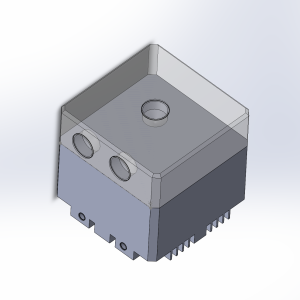
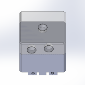
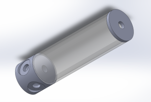
    • Custom part dimensions verified and adjusted to match real measurements
    • Plan to send out custom cut parts after Fall Break
  • Behind schedule:
    • UART Pi5-Pico communication delayed due to debugging
    • Minor delays from Pi5 setup and network configuration issues

Next Steps

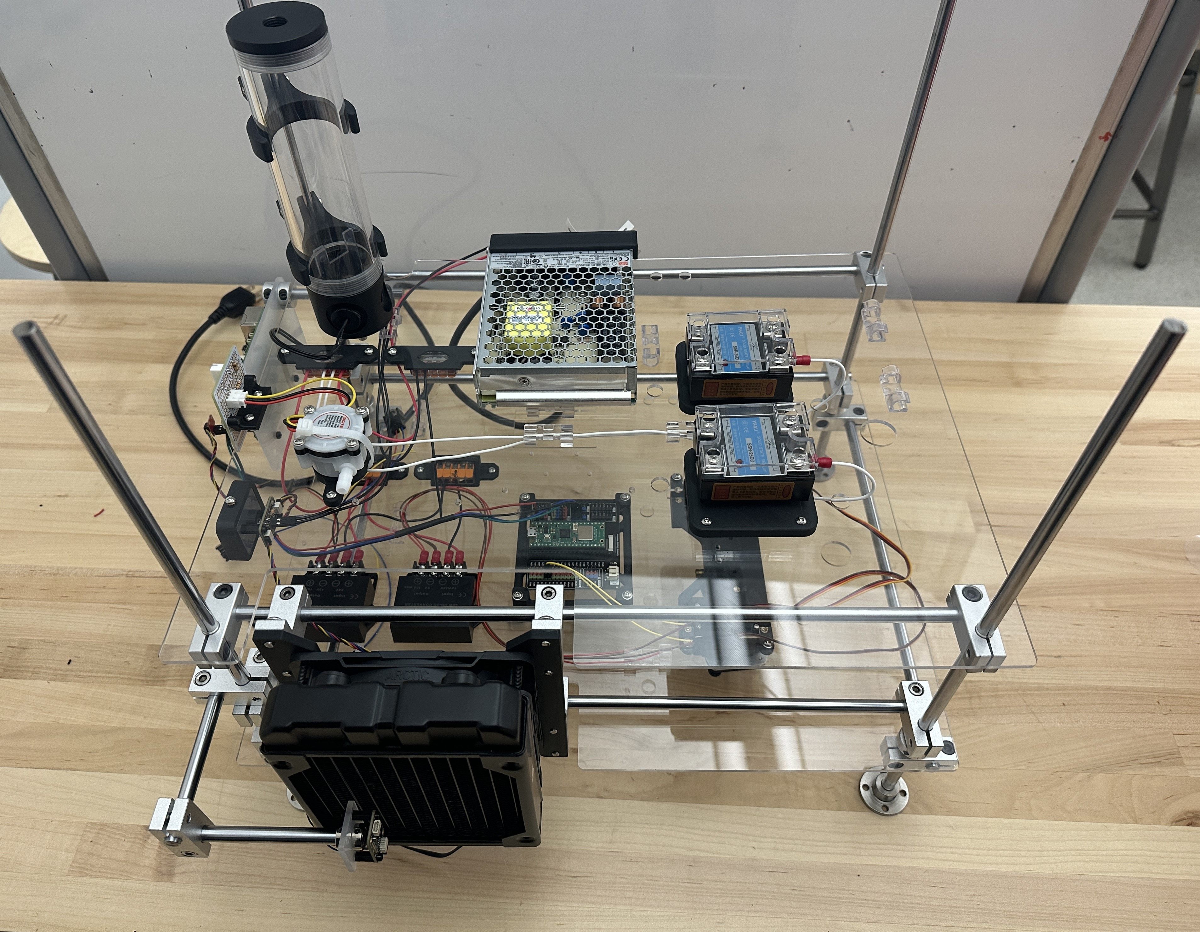
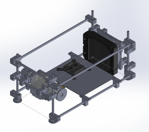
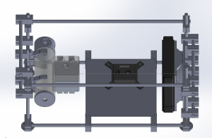
  • Begin setup and partial assembly of testbed
  • Continue debugging UART communication
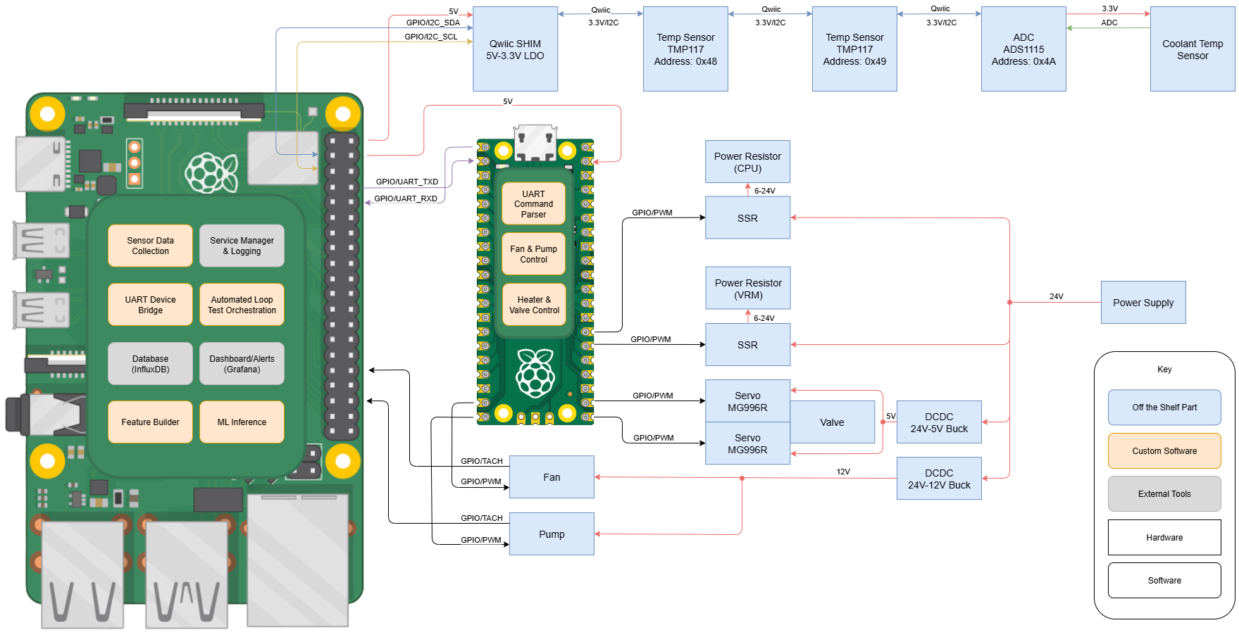
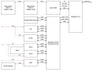
  • Assist with sensor integration and PWM control code

Kristina’s Status Report for 10/04/2025

Raspberry Pi Setup

  • Set up Raspberry Pi 5 for future UART communication with Pi Pico code development
  • Troubleshot several setup issues:
    • Broken mini-HDMI cable causing monitor display issues
    • Missing microSD reader, preventing Pi OS installation through the Pi Imager
    • SSH connection issues due to the wired ethernet network being different from CMU Secure wireless
  • Successfully imaged Pi OS onto the microSD card and completed initial configuration at home before bringing the Pi back to campus, which resolved network issues

Parts Procurement

  • Ordered off the shelf components listed in the BOM
  • Currently waiting for parts to arrive before verifying part dimensions and fabricating laser cut mounting plates

Design Report and Research

  • Worked on Design Report sections covering use case and requirement justifications
  • Found IEEE Xplore papers related to anomaly detection to reference for style and technical wording in the Design Report

Schedule & Progress

  • Currently slightly behind schedule due to:
    • Waiting for hardware parts to arrive before starting laser cut fabrication
    • Delays in Pi 5 setup and network access during initial configuration

Next Steps

  • Begin laser cut fabrication once parts (specifically the pump) arrive
  • Continue 3D printing remaining brackets and verify fits
  • Start Pi 5 to Pico UART code development
  • Finish Design Report as soon as possible to get feedback

Kristina’s Status Report for 09/27/2025

Completed CAD Model

  • Completed CAD model with water loop and other component models downloaded from online (e.g. SSRs, DC-DCs, etc.)
  • Adjusted radiator + fan position to reduce board size
  • Planned out and added power planes (24V power supply stepped down to 12V, 5V for fan/pump, servo)
  • Began 3d printing some parts from CAD design
    Full Assembly
    Full Assembly – Bottom View
    Water Loop
    Heater Complex (Power Resistors)
    Servo Valve Assembly (Blockage Fault)

    Power Distribution

Block Diagram

  • Finalized block diagram to add power supply and conversion
  • Adjusted coolant temp sensor connection to separate sensor data collection from controls (fan/pump, valve, heater)
  • Added software

    Block Diagram

BOM Draft

  • Completed BOM, added case components like linear motion rods and connectors
  • Added power components like DC-DC converter, power supply

Schedule & Progress

  • Updated schedule to account for part lead times
  • Need to order parts ASAP since fabrication for laser cut parts depend on dimensions of actual mounting holes

Next Steps

  • Begin ordering off the shelf components from BOM
  • Work on design report

Kristina’s Status Report for 09/20/2025

Block Diagram Draft

  • Made first draft of block diagram showing connections between sensors, Raspberry Pi 5, Pi Pico, SSRs, power resistors, servo valves, and cooling components
Block Diagram v1

BOM Draft

  • Made first draft of BOM listing major components based on block diagram and physical assembly, to be updated

CAD Models of Liquid Cooling Components

  • Found online CAD models of radiator, fan, and water block
  • Altered radiator model to better match actual part
  • Created CAD models for pump and reservoir based on product photos and references
Pump CAD Model – Side View
Pump CAD Model – Bottom View
Pump CAD Model – Top View
Reservoir CAD Model

Initial CAD Assembly of Cooling Loop

  • Built an initial CAD assembly of liquid cooling loop with component models
  • Used linear motion rods and connector system for structural frame
Case Assembly v1 – Left View
Case Assembly v1 – Top View
Case Assembly v1 – Right View

Revised CAD Assembly of Cooling Loop

  • Updated initial assembly to accommodate sensor placements, including radiator intake/exhaust temperature sensors and mounting space for Raspberry Pi 5 and supporting components
Case Assembly v2 – Front View
Case Assembly v2 – Side View
Case Assembly v2 – Back View

Schedule & Progress

  • Currently on schedule
  • CAD modeling, assembly, block diagram, and BOM align with Gantt chart

Next Steps

  • Iterate on block diagram
  • Expand BOM to include linear motion rod and connectors
  • Start purchasing off the shelf parts in order to update CAD assembly with corrected dimensions and order 3D print/laser cut parts