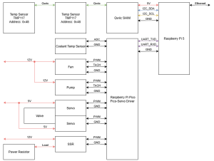
Made first draft of block diagram showing connections between sensors, Raspberry Pi 5, Pi Pico, SSRs, power resistors, servo valves, and cooling components
Block Diagram v1
BOM Draft
Made first draft of BOM listing major components based on block diagram and physical assembly, to be updated
CAD Models of Liquid Cooling Components
Found online CAD models of radiator, fan, and water block
Altered radiator model to better match actual part
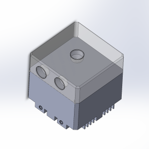
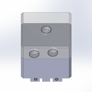
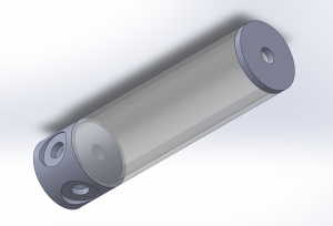
Created CAD models for pump and reservoir based on product photos and references
Pump CAD Model – Side ViewPump CAD Model – Bottom ViewPump CAD Model – Top ViewReservoir CAD Model
Initial CAD Assembly of Cooling Loop
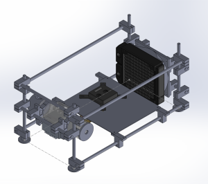
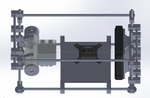
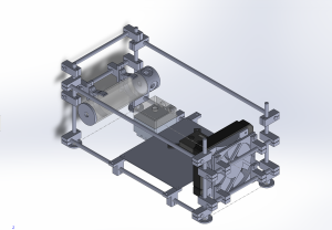
Built an initial CAD assembly of liquid cooling loop with component models
Used linear motion rods and connector system for structural frame
Case Assembly v1 – Left ViewCase Assembly v1 – Top ViewCase Assembly v1 – Right View
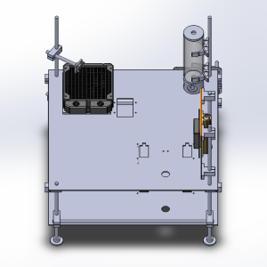
Revised CAD Assembly of Cooling Loop
Updated initial assembly to accommodate sensor placements, including radiator intake/exhaust temperature sensors and mounting space for Raspberry Pi 5 and supporting components
Case Assembly v2 – Front ViewCase Assembly v2 – Side ViewCase Assembly v2 – Back View
Schedule & Progress
Currently on schedule
CAD modeling, assembly, block diagram, and BOM align with Gantt chart
Next Steps
Iterate on block diagram
Expand BOM to include linear motion rod and connectors
Start purchasing off the shelf parts in order to update CAD assembly with corrected dimensions and order 3D print/laser cut parts