This week, I mainly focused on preparing for the final presentation. We compiled all of our data from testing and created tables to show them in the slideshow. Additionally, I compiled a list of trade-offs that we faced throughout the iteration process as well as information on group studies we conducted. After the presentation, I helped create a final poster to show off our design and work throughout the semester, and made some finishing touches to the information presented as well as documenting the complete solution of our product. Next week, we will work on the demonstration as well as finishing up the final design report. We will also gather any information needed for these presentations as well as conduct any more testing necessary to meet design requirements. We are well on schedule for this week.
Sarah’s Status Update 12/2
This week, I mostly focused on getting all of the sensors onto the glove itself. I helped in soldering wires onto the sensors as well as soldering them directly onto the board. I measured roughly and made sure there was enough wire to reach the board on the back of the hand. After this, I tested each sensor to make sure they were still working, and then gave it to a small user group to try out. One of the most concerning responses was that when the user reached up to squeeze the touch sensors, it would accidentally trigger the flex sensors, since the finger naturally bends to touch finger pads with another. I experimented more with the placement of each sensor on the glove, and we decided to move all the sensors down so that the touch sensors were easier to reach and the flex sensors would only trigger with drastic finger flexes. After this, I experimented with actuating certain commands with the sensors, and it worked fairly well. Additionally, I toggled with the thresholds of what we consider a press or not, and mapped them more closely with this new placement of sensors. I also started working on the slides for the final presentation as well as practicing my speech during the presentation. We are currently on schedule and will be able to present next week for the final presentation. Next week, I will work on fine tuning the thresholds and adding a way for the user to calibrate the sensors to their liking.
Sarah’s Status Update 11/18
This week, I worked more on interfacing the sensors with the board. I was able to solder some wires to the sensors to wires for them to connect to the board. Additionally, I did more research on the sensors and their resistance limit. I’m fairly sure the resistors I put in place (10K) will suffice for any amount of combination for sensor resistances, but I will also look into increasing the resistance limit for more calibration purposes. I also explored the layout that we would like to use for the sensor and board placement on the glove. Next week, I will focus on soldering the PCB since it will likely arrive in the next few days, and attaching everything to the glove for a working model. We will also decide on which battery to use, as we would like it to be as light as possible. We are looking into 5V batteries with around 2000mAh since our tests indicated this would be sufficient power for more than 2-3 hours, which was our requirement. We will most likely order a backup battery and connect via usb. We are largely on track for this project and will look into getting more data and running more tests when the board arrives.
Sarah’s Status Update 11/11
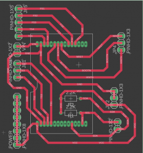
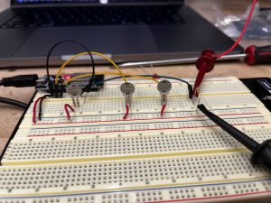
This week, we had our interim demonstrations, so I worked on getting ready for that. I set up a breadboard with 4 touch sensors and 3 flex sensors and connected them all to the ESP32. However, the flex sensors’ resistance was too large to be recognized by the ESP. I then added 10K Ohm resistors in parallel for each flex sensor to lower the effective resistance of each flex sensor circuit. Additionally, when combining all the sensors on the same power line, there seemed to be the same problem with too much resistance on each line. I then added 10K Ohm resistors in parallel for each sensor, which seemed to solve our problem. We also received our IMU earlier this week. Since the communication between the ESP and IMU is I2C, I created an I2C scanner to find the peripheral address of the IMU. I then read through the IMU manuals to figure out how to enable and display the readings from each sensor on the IMU. Since the IMU is the only peripheral on the I2C bus, I treated it as a sensor and constantly polled for data. This eliminated the need for interrupts, so the only wires connecting the ESP and the IMU are power, mode selection for the communication protocol, and the data and clock lines. We ended up implementing a library especially designed for the FSM300, which allowed us to print gyroscope and accelerometer readings to the serial display. After adding in the resistors to the demo breadboard, I updated the PCB files to include these added resistors, using SMD 0805 10K resistors. For ease of use and to make our entire footprint smaller, I sent out the files for the PCB to be fabricated, and I expect this order to arrive early next week. I also placed an order for the correct resistors needed as I will do the PCB assembly by hand. Finally, I tested out the battery life needed for the entire system, and found that the battery life lasted for over 15 hours with about 7500 mAh of charge. Next week, I will start assembling the PCB, attaching the sensors to the glove, and do some more stress testing on the battery so we can hopefully order either a small power bank or lithium ion battery for the final project. We are on schedule to finish on time.
Sarah’s Status Update 11/4
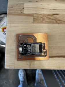
This week, I worked on polishing the PCB we have for the project. I made the traces larger on the schematic for power routing, and realized that the reason why our PCB kept short circuiting was because it was a two sided PCB. Next steps for next week would be to sand off the bottom of the PCB and solder on the pin headers needed for the board. We received the IMU as well and starting tomorrow I will working on interfacing the main board with the IMU, setting up I2C communication, and figuring out how to derive information from the IMU. Since we already soldered jumper wires to the IMU, I will need to connect the reset, interrupt, power, ground, and communication pins to the ESP32. There were no considerable changes made to our final design, and we are still on track for our final presentation. We will work on patching up our design and creating a demonstration for the interim demos next week.
Sarah’s Status Update 10/28
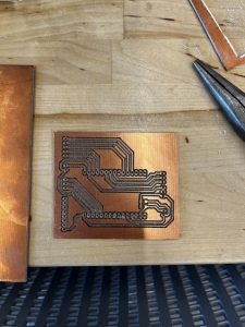
This week, I focused on creating the schematic, gerber files, and PCB for our project. This was mainly for routing power, connecting the ESP more easily to peripherals, and creating a hub where most of our components lie. I created a schematic on Fusion 360 with female pin headers for the ESP32, and male headers for each of the peripherals to connect to. Then, I used the milling machine in Techspark to create a PCB we could use. Unfortunately, it seems like our board is shorted somewhere, but I have yet to test it extensively to figure out where the short lies. I faced lots of problems with creating this PCB, including:
- The distance between the two pin headers for the ESP32 was too large, so I had to iterate on the design multiple times to make sure the board fit securely.
- I originally routed the PCB to use two sides, but after finding out the PCB milling machine only mills out one side, I had to recreate the board using only one layer. Since there are lots of peripherals, it was hard to find a configuration that didn’t overlap with other traces.
- The milling machine has a large learning curve, so I had to print the PCB at least 6 times before I got the hang of how to use it effectively.
- The milling machine has very specific rules on how close traces can be as well as traces coming out of pin headers, so making sure these rules were followed was also difficult.
Since the board has a short, next week I will focus on figuring out whether the short comes from the PCB itself, or if it is a problem with the schematic I created. In terms of hardware, we are still on schedule with the project, and we are still awaiting arrival for the IMU. Our flex sensors came in the mail earlier last week, so we are also looking forward to testing and connecting these sensors to the ESP3210
Sarah’s Status Update 10/21
We figured out we needed a PCB to interface the microcontroller with the sensor peripherals we have as well as the IMU. This week, I started working on the PCB design we need for the board. I created a part on Fusion 360 for the ESP32 development board, as well as a footprint and 3D model. After that, I started working on creating a layout for where we want each peripheral to connect to the board and the power routing for each sensor. Since this week we scheduled for slack, we are still on schedule. We are awaiting arrival of the IMU we ordered so we can start interfacing via I2C and experimenting with the various sensors on the board. In the next week, we hope to receive the IMU, and start interfacing it with the ESP32.
As for new tools we are currently looking into for the project, I am personally looking more into PCB fabrication, specifically using a PCB milling machine to make our new board for interfacing. Hopefully after researching the required software, I will be able to create a PCB that is suitable for our purposes and fits the ESP32 development board correctly.
Sarah’s Status Update 10/7
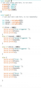
This week, we received our board (ESP32S) and touch sensors. I started testing out the board to see how we could boot it and ended up using Arduino IDE to code. I created a simple testing structure where we could measure the relevant thresholds for each sensor and validate their functionality. I connected a touch sensor each to an ADC pin and outputted a prompt when each sensor was triggered. Some notes found were:
- When not triggered, each sensor has a different value, but all seem to be under 1000 after ADC calculations, so for validation purposes we set our thresholds to this value.
- When pressed, each sensor value reaches to on average 4000 after ADC calculations, but one of the sensors only seemed to reach 2000 with similar force.
- There seems to be a bit of variance throughout each sensor for values, so we will have to document which sensors these are and do slightly different calibrations for each sensor.
Additionally, after some confusing results, I discovered that two of the pins on the board were shorted together, pins D4 and D15, which unfortunately are both ADC pins. Since we’re not exactly sure the orientation of each sensor relative to the board, we will need to purchase a different board for the final design.
Since we have finished thresholding and setting up the sensors, we are on track for the project. Next week, we plan on receiving the other sensors and starting on IMU calculations, while also starting to map out specific placement for the sensors on the glove and how they interact with the board. I also realized during this process that we will likely need to create and order a PCB for power and signal mapping, so I will start on this next week as well.
Sarah’s Status Update 9/30
This week, I further researched the right microcontroller to use for the project, and we’ve settled on the ESP-32S board. This is because there are more than 12 ADC inputs on the board, which is more than enough for our sensors, it has built in Wi-Fi and bluetooth, supports Arduino IDE and comes in a compact size of just over 2 inches. We’ve already ordered the board and it will come early next week. As such, I am a bit behind schedule since we were unable to receive the board this week. To make up for this, I will start interfacing with the board when it arrives, but further research on the board suggests the setup process is quite seamless when using Arduino IDE, so I don’t expect this process to take longer than a day. Additionally, I created a block diagram for the design we will use for the sensor to board interface, and started creating a schematic for the design report for next week. I researched different power sources we could use, including coin cells and lithium ion batteries. After researching the power consumption needed for each component, we have a ballpark estimate of how many mAh we need to sustain our device for our target battery life of 2-3 hours. Since we have already ordered the sensors needed as well, next week we will start interfacing the sensors with the board, and experimenting with different thresholds for the analog inputs. Intro to Embedded Systems greatly helped with the block diagram and schematic design for our project. Additionally, Electronic Devices and Analog Circuits helped me to better understand power rules and create circuit diagrams for the power structure.
Sarah’s Status Update 9/23
This week, we gave a presentation on our project proposal. We received good feedback on our design requirements, especially the concern about the size of the board we originally picked, the STM32 Nucleo Board. We decided to look into other options for our main board, including an Arduino Uno, for its ease of use. However, we realized that for the sensors we require, we would need around 8 analog inputs (not including the IMU inputs), which is 2 more than is included on the Arduino Uno. From here, we explored other options, such as analog multiplexers to switch between each sensor input, switch matrices to utilize the 6 analog inputs on the Arduino for 9 analog signals, or a PCB with extra ADC’s. We are still in progress of choosing a main board for the project, but the feedback we received was helpful in our research. Additionally, we chose the sensors we need for the project, and are working to order them in the coming days. We are still on schedule for the project, and we hope to receive some parts by next week to test compatibility and start setting up drivers for the main board.