This week, I wrote the code that processes the IMU data. I’m just waiting for the IMU to come in so that I can test it and alter values. I’ve started looking more into PyAutoGUI so that it can soon be integrated with the IMU code. We are still on schedule since we are confident in the code currently, but just need to test it. Next week I hope to have the IMU and start getting it to read the values and hopefully get it generally working.
Team Status Update 10/28
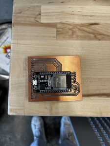
This week, we planned out our code for when we receive our final set of sensors. Sarah also finished routing and milling our PCB. In terms of the risks that our project currently faces, we still haven’t received our IMU, so we can’t start fully coding that part yet until we can figure out and play around with the IMU’s calibration and sensor outputs. We are also facing issues with the PCB – specifically, Techspark’s PCB mill was not accurate enough for our small PCB, and we identified shorts between the traces on the board. We are planning on either using a vector board or ordering our PCB, but with the increased shipping time, we are a little bit worried about how this will affect the timeline of our project. We plan to make our decision about the board by Monday when we can place orders, and update our timeline accordingly if necessary.
Sarah’s Status Update 10/28
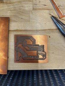
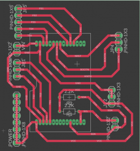
This week, I focused on creating the schematic, gerber files, and PCB for our project. This was mainly for routing power, connecting the ESP more easily to peripherals, and creating a hub where most of our components lie. I created a schematic on Fusion 360 with female pin headers for the ESP32, and male headers for each of the peripherals to connect to. Then, I used the milling machine in Techspark to create a PCB we could use. Unfortunately, it seems like our board is shorted somewhere, but I have yet to test it extensively to figure out where the short lies. I faced lots of problems with creating this PCB, including:
- The distance between the two pin headers for the ESP32 was too large, so I had to iterate on the design multiple times to make sure the board fit securely.
- I originally routed the PCB to use two sides, but after finding out the PCB milling machine only mills out one side, I had to recreate the board using only one layer. Since there are lots of peripherals, it was hard to find a configuration that didn’t overlap with other traces.
- The milling machine has a large learning curve, so I had to print the PCB at least 6 times before I got the hang of how to use it effectively.
- The milling machine has very specific rules on how close traces can be as well as traces coming out of pin headers, so making sure these rules were followed was also difficult.
Since the board has a short, next week I will focus on figuring out whether the short comes from the PCB itself, or if it is a problem with the schematic I created. In terms of hardware, we are still on schedule with the project, and we are still awaiting arrival for the IMU. Our flex sensors came in the mail earlier last week, so we are also looking forward to testing and connecting these sensors to the ESP3210
Saumya’s Status Update 10/28
This week, I worked on trying to get communication between the ESP32 and our Python receiver to work via BLE. I also helped Sarah talk through some ideas while she worked on our PCB. I wasn’t able to get Bluetooth to work with my M1 even using a different Python package, so I may fall back on our backup plan of either using a VM/different OS or trying WiFi with the ESP32. I also worked on the ethics assignment individually and with my group for the group discussion portion. I was unfortunately sick for most of the week as well, so I am a bit behind schedule with regards to our Gantt chart. To get back on track, I will spend the first half of the week catching up with my other classes including a makeup exam until Tuesday, and then dedicate the rest of the week to working on capstone. During my breaks in the first half of the week, I’ll also read up on WiFi projects and set up my VM so I can get started with our backup plans as soon as Wednesday hits.
Rosina’s Status Update 10/21
This week was assigned as slack week for us. This week I did some more research on the IMU and PyAutoGUI since we hope to receive the IMU component soon and I want to make sure that we’re ready to use it. We are still on schedule. For next week, I hope to start playing around with the IMU and look at the calibration software that is comes with. As for new tools to learn, I primarily want to focus on PyAutoGUI and reading the IMU data.
Saumya’s Status Update 10/21
This week was our budgeted slack week. We largely used this time to enjoy our break since we’re mostly on track, but we did a small amount of work to keep progressing towards our Gantt chart goals. Specifically, I looked into sample projects using the ESP32 and Bluetooth and downloaded the required Bluetooth modules. To work with my M1, I determined that I wouldn’t be able to use the bleak package, but pybluez might be compatible. As per the Canvas question, I’m looking into learning the Bluetooth protocol (at the abstracted level of the ESP32 and Python modules) as well as programming for the ESP32 in particular.
Sarah’s Status Update 10/21
We figured out we needed a PCB to interface the microcontroller with the sensor peripherals we have as well as the IMU. This week, I started working on the PCB design we need for the board. I created a part on Fusion 360 for the ESP32 development board, as well as a footprint and 3D model. After that, I started working on creating a layout for where we want each peripheral to connect to the board and the power routing for each sensor. Since this week we scheduled for slack, we are still on schedule. We are awaiting arrival of the IMU we ordered so we can start interfacing via I2C and experimenting with the various sensors on the board. In the next week, we hope to receive the IMU, and start interfacing it with the ESP32.
As for new tools we are currently looking into for the project, I am personally looking more into PCB fabrication, specifically using a PCB milling machine to make our new board for interfacing. Hopefully after researching the required software, I will be able to create a PCB that is suitable for our purposes and fits the ESP32 development board correctly.
Team Status Update 10/21
This week was our budgeted slack week as per the Gantt chart. In terms of the risks that our project currently faces, we are a little worried about the shipping time for the IMU and the printing time for our PCB. We ordered the IMU right before break, and we are hoping that it’ll get delivered by the time we get back. As for the PCB, since Techspark was closed this week for break, we couldn’t get a head start on milling our PCB. If we can’t get the PCB milled, we can test with a breadboard until we get the PCB. If the IMU doesn’t arrive, we’ll need to move things around a little to budget more time to play around and code for the IMU. We haven’t made any changes to the design in the past week except deciding to mill the PCB ourselves instead of getting it outsourced.
Rosina’s Status Update 10/7
This week my team delivered the design presentation. We spent most of this week on the design since we have the report due this week. This week, I got more comfortable with using PyAutoGUI and its features, so I moved on to looking into IMUs. Our group received the parts that we ordered today, but we have yet to order an IMU since we still haven’t decided on the capabilities it needs. During the design presentation we also received a question on IMU acceleration calculations that we didn’t know the exact answer to, so I spent a majority of this week researching IMU calculations. We are still on schedule according the the Gantt chart, and this upcoming week I hope to solidify the design since the design report is due. In addition to that I hope to decide on an IMU and be fully prepared to use it when it arrives.
Sarah’s Status Update 10/7
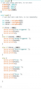
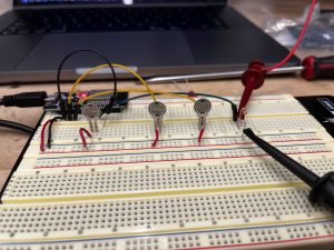
This week, we received our board (ESP32S) and touch sensors. I started testing out the board to see how we could boot it and ended up using Arduino IDE to code. I created a simple testing structure where we could measure the relevant thresholds for each sensor and validate their functionality. I connected a touch sensor each to an ADC pin and outputted a prompt when each sensor was triggered. Some notes found were:
- When not triggered, each sensor has a different value, but all seem to be under 1000 after ADC calculations, so for validation purposes we set our thresholds to this value.
- When pressed, each sensor value reaches to on average 4000 after ADC calculations, but one of the sensors only seemed to reach 2000 with similar force.
- There seems to be a bit of variance throughout each sensor for values, so we will have to document which sensors these are and do slightly different calibrations for each sensor.
Additionally, after some confusing results, I discovered that two of the pins on the board were shorted together, pins D4 and D15, which unfortunately are both ADC pins. Since we’re not exactly sure the orientation of each sensor relative to the board, we will need to purchase a different board for the final design.
Since we have finished thresholding and setting up the sensors, we are on track for the project. Next week, we plan on receiving the other sensors and starting on IMU calculations, while also starting to map out specific placement for the sensors on the glove and how they interact with the board. I also realized during this process that we will likely need to create and order a PCB for power and signal mapping, so I will start on this next week as well.