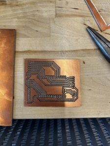
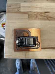
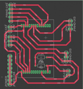
This week, I focused on creating the schematic, gerber files, and PCB for our project. This was mainly for routing power, connecting the ESP more easily to peripherals, and creating a hub where most of our components lie. I created a schematic on Fusion 360 with female pin headers for the ESP32, and male headers for each of the peripherals to connect to. Then, I used the milling machine in Techspark to create a PCB we could use. Unfortunately, it seems like our board is shorted somewhere, but I have yet to test it extensively to figure out where the short lies. I faced lots of problems with creating this PCB, including:
- The distance between the two pin headers for the ESP32 was too large, so I had to iterate on the design multiple times to make sure the board fit securely.
- I originally routed the PCB to use two sides, but after finding out the PCB milling machine only mills out one side, I had to recreate the board using only one layer. Since there are lots of peripherals, it was hard to find a configuration that didn’t overlap with other traces.
- The milling machine has a large learning curve, so I had to print the PCB at least 6 times before I got the hang of how to use it effectively.
- The milling machine has very specific rules on how close traces can be as well as traces coming out of pin headers, so making sure these rules were followed was also difficult.
Since the board has a short, next week I will focus on figuring out whether the short comes from the PCB itself, or if it is a problem with the schematic I created. In terms of hardware, we are still on schedule with the project, and we are still awaiting arrival for the IMU. Our flex sensors came in the mail earlier last week, so we are also looking forward to testing and connecting these sensors to the ESP3210


