Emily’s Status Report 10/9/2021

I gave the design review presentation this past Wednesday, so I spent the days leading up to it practicing.

Earlier this week, I figured out what values for the LC circuit we would need with the 8V step down. I picked out the batteries that we are going to use to power the circuit (2x 12V 30Wh batteries). Besides that, I filled out the data for the order forms (waiting to confirm with the others before submitting). I’ve also ran through our entire system a couple times (component wise) to try to make sure that everything has compatible communication ports, has power, etc. In doing so, I took a lot of notes on things that will hopefully be of use for our design document.

Team Status Update 3 OCT 2021

The main focus of our team this week was making some final selections of in preparation for our design review. A lot of this focus was around our sensor. At the beginning of the week, we were looking into transitioning away from a rotating LIDAR Sensor to an array of stationary LIDAR and ultrasonic sensors, but after a thorough review of this idea and the introduction of the possibility of the use of microwave sensors, we decided to move to the newer microwave technology. The sensors we selected will give us a 20m range without the sensitivity to light that concerned us with the LIDAR sensors. The sensors have a horizontal 3db beam width or 78 degrees, meaning a small array of such can easily cover our field of view. The sensors can also track multiple objects, though they only give back distance information without any information concerning the look direction.

We also looked at the lights to be used for signaling and the draws this would have on power. Though we had found some promising looking single point LEDs they had low efficiency, so we have currently transitioned back to using an LED strip both in the front and back. Our want for a full day of use and the large draws of both these LEDs and the sensor will require a rather large battery. Some discussion has also been had about using an Arduino in conjunction with the STM32F4 to run the lights, and it has also tentatively been decided that the signals processing interface and code will be written in C code.

Design review slides to be amended later or posted separately.

Emily’s Status Update 10/3/21

This week I figured out how much capacity the battery for our system would need. To do so, I found the current draw from each of the components. In doing so, I learned about luminous efficiency and determined that the LEDs that we were planning on using were extremely inefficient. Considering that our system is run off of a battery, conserving power is very important, so I picked out another set of LEDs. I decided to go with addressable LED strips because they had a higher luminous efficiency (above 100 lumens/W, which is acceptable for red LEDs) and they would allow us to output more light over a wider area, as well as adjust their output if necessary.

Once I found the LEDs that we were going to use, I combined their current draw with that of the other components, giving us a maximum current draw of 5.5 A. This number is much higher than what our average current draw should be, considering that the lights won’t always be on and they won’t be outputting their full RGB spectrum. Additionally, we will have an on/off switch for the system overall, so we won’t need to power 5.5 A for 10 hours. Thus, with 1 hour of on time and 8 hours of standby/off, that should give us at least a 5Ah battery.

This week I also worked on the slides for the presentation. I updated the schedule, the overview drawing, and added some drawings. I also will be giving the presentation so I practiced presenting.

Jason’s Status Report 10/2

This week, my teammates and I were able to mostly finalize the parts that we will be using for our project. I proposed the use of a microwave sensor to the team, and after discussions and research about its abilities and pros and cons, we decided to switch our design to an array of 2 microwave sensors. To potentially reduce code complexity, we also added an Arduino to our system in order to drive the LEDs using manufacturer drivers, since those are readily available for Arduino.

The progress in deciding parts has enabled me to confirm that the STM32 development board we initially picked out has enough ports to read inputs on both microwave sensors and control the Arduino LED driver, and enough capability to process the required data.

I had discussions with Albany, who is currently working on signal processing code, about the potential need to store many scans from the sensor to accurately filter out the ground, which  might be present in our microwave sensor readings. We concluded that it will not be of an immediate concern, since we have 512KB of memory to work with, while each data array from both microwave sensors is only 252 bytes long. We also decided on using C to develop the algorithm, with more complex processing written in Matlab and generated into C code.


Albany’s Status Report 2 OCT 2021

For most of the week I have been looking into sensors with my team to make final determinations for what should be used for our blind spot sensor. At the time of my last status report we were looking into a mix of long range single point LIDAR sensor and ultrasonic sensors, so I started the week by coming up with a possible arrangement for an array of sensors that used two of each kind. This arrangement is can be seen in document V2: V2SensorPlacementLIDARULTRA

However, following a suggestion for the use of a 24GHz microwave sensor from Jason, and some research into that solution and discussion of the pitfalls and merits of all solutions we had discussed prior to it, we decided to make our primary solution an array of at least two microwave sensors which we filled out the form to order during class on Wednesday. I have since been familiarizing myself with how that sensor presents distance information. It appears as though the sensor will allow us to determine the distances of multiple objects, but not their particular look directions. With two sensor this means that though we can cover our entire FOV as the sensors have a 3db beam width of 78 degrees, the most information we can give back to the user is which sensor detected the object. However, this still allows us to tell the user if something is behind them to the right or left. Further, by looking at a possible overlapped area of the sensors, a third sector for objects seen by both sensors could be achieved. Some of my initial thoughts into the example code provided by the manufacturer for multi-object detection and a basic layout of the signals processing code to handle information can be seen in document V3: V3ManCodeCustomCodeStructureMicrowave

Me and my teammates are planning to get together later today to edit/create our design presentation slides and I hope to also determine with Jason who is in control of the device drivers what language we plan to use so that I can code up most of the signals processing code this week. Possibly with the exception of the code to filter out any “noise” from the ground as some baseline data from the sensors will be useful before adding that section.

Emily’s Status Report 9/25/21

Because we have decided to change a lot of the hardware components of our system, I’ve looked into options for those changes.

We also have a concern about distracting the cyclist with the LEDs on the handlebars, so I’ve also looked into other indicator options. Vibration was suggested, but for a safety critical system, vibration is too unreliable considering that roads aren’t smooth and that in different weather conditions, the rider might be wearing gloves that could dampen the vibration. Audio was also suggested as a method of communicating to the rider. Audio queues would have to be repeated and run the risk of being too quiet to be heard clearly over city noise. There would also be cases of emergency vehicles causing very loud noise and cyclists wearing earphones. I looked into ways of mitigating the dangers associated with the LEDs, specifically their brightness in the dark. We can use diffusers so that the light doesn’t shine directly into the eyes of the cyclist. The diffusers will require that we pick out brighter LEDs since they decrease the output by 2-6%.

We have also decided to move away from the planned PCB for the system and to use an eval kit instead based on TA advice. This will allow us to better make changes to the system as problems arise. I haven’t used an eval kit before, so I spent some time looking into how to use/build with them. Overall, my schedule can now be moved forward somewhat since we won’t have to wait for shipping and can assemble and debug as soon as the parts are in. I’ve started work on the schematic, but the changes to the sensors and the LED response system need to be finalized before I can finish.

Team Status Report 9/25/21

This week we’ve had a lot of hardware updates to our project idea based on the feedback that we received from our project proposal. We are looking into using a static sensor array rather than a single 360-degree LIDAR sensor. This will hopefully allow us to update the system of new inputs more often.

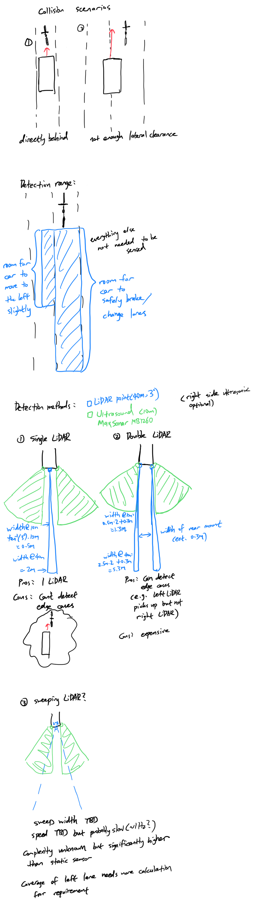
We are also looking into using both ultrasonic sensors and LIDAR. LIDAR gives us more detection distance (up to 40m in favorable conditions) yet is less reliable in bright lighting conditions and could be affected by our LED indicators on the back. The ultrasonic sensors can’t cover as much distance as the LIDAR sensors but aren’t affected by the LED indicators. We plan on using them as the primary short-range sensor, ~10m or less. That way, when we have the LED indicators on, we know that the sensing isn’t being adversely affected.

We had originally planned on using a LED strip because the 360-degree LIDAR would give us enough information to report where the nearby objects were with more granularity. However, especially since we are switching to static sensors, we decided that we aren’t going to attempt to provide that much information. This will help us not overload the cyclist with excess information: the cyclist doesn’t need to know the width of the object closing in behind them, they just need to know that there is something generally to the back left, the back right, or behind them. More to this point, we have decided to go with zone LED indicators-similar to what you’d see for the side indicators for a car.

We received some questions about how exactly we are going to communicate to the cyclist about the conditions behind them. We plan on using a system where a steady light in a zone indicates the presence of an object that is tracking behind them, while filtering out stationary objects. Then, when there is what we consider a danger, like something closing in fast or that is very close to the bike, we are going to flash the LED of that zone. We are cognizant that we need to pick out LEDs that are bright enough to work in daylight conditions, while also not blinding/distracting the cyclist, especially at night.

From here, we are going to research these changes and their practical brand options, and integrate them into our design.

Jason’s Status Report Sep.25

This week we were able to successfully deliver our presentation, and soon after that we received feedback about some aspects of our technical design, particularly our choice of a rotating LiDAR to be used in outdoor conditions.

We had discussions as a team and, factoring in feedback from the professor and the TAs, started taking the idea of static sensor arrays more seriously, and I came up with some possible solutions that will enable us to satisfy our sensing requirements with much more reliable and long-range sensors.

I thought the biggest challenge using static sensors is losing resolution, however, running through some scenarios, I discovered that, since cars are quite large, we can safely assume that the closest object to our sensors would be a car. The only issue, then, is detecting if the edge of a car might collide with the biker. To mitigate this issue, I conceived of some concepts for sensor arrangement attached to this post.

For the next steps, we will calculate the exact requirements for sensing in different scenarios  and pick the most favorable arrangement of sensors based on that.

Albany’s Status Report 25 SEP 2021

As I was the presenter for our project proposal, prior to Wednesday, I spent this week predominately practicing my presentation and delivery to make sure I wouldn’t forget any pertinent details and would stay on schedule when speaking.

Following the presentation, I started working on some of the basic signals processing considerations for the sensor, attempting to figure out some basic cutoffs for showing sensed objects to the biker and trying to consider what issues might arise. One of the things I foresee might be especially problematic will be filtering out stationary objects.

Further following some comments from the professors and staff, and a small back and forth, the team is looking into other sensor options than the RPLIDAR and we are getting together later today to discuss some of the suggested options. One possible solution, were we to assure we had the budget for it, that I started looking at was using a mix of longer range lidar sensors to first detect the object in certain common look directions and then a set of ultrasonic sensor to give us a more complete FOV if necessary and be able to track when warning lights on the tail mount might interfere with the LIDAR.

Some of my thought process can be seen here: SignalsProcessingSensorConsiderations25SEP