
Final Video 12/12/2021
Jason’s Status Update 12/4
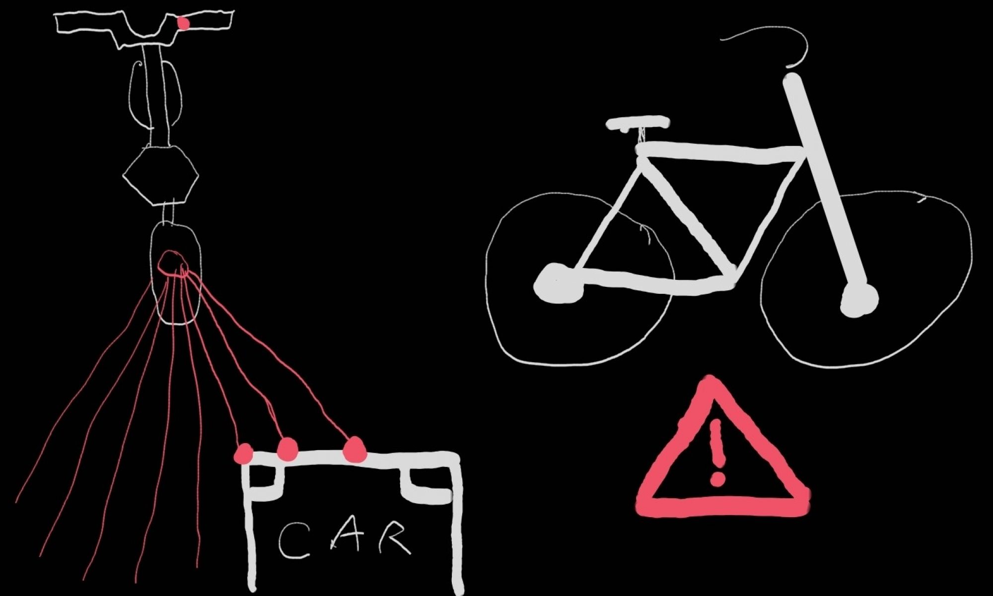
Since Thanksgiving, I have been working hard to engineer a GPIO-based solution to transmit LED codes as required in the design, in order to circumvent the problems we had with serial communication. That has since been finished and tested. Although there are some problems working with the full set of LED control routines on the Arduino, a reduced set works and the oscilloscope measurements from the STM look normal, so we’ll have to look on the Arduino further to solve this problem.
I also helped with the assembly of the system, soldering and heat-shrinking some wires from the STM to the Arduino and sensors. The assembly was completed and I managed to load a version of code into the system that controls the front LED lights accurately reflecting sensor readings and signal processing results. This marks the completion of the duties that were assigned to me, so I can now dedicate my time to help with testing and debugging as part of the final step of the project.
Team Status Update 12/4/21
Last week, we got the system running off of battery power. We’ve added JST-SM connectors to the batteries and the LED power connectors so that we can disconnect and debug more easily. The ON/OFF switch has been connected to the solder board, and the turn signal button has been connected as well. All of the hardware has been connected. The final mount will be printed next week so the physical component of the project will be finished after that is printed.
We’ve been having some problems with the communication between the STM and the Arduino. The GPIO from the STM works, but the Arduino code needs to handle the data more quickly for us to meet our timing requirements. Next week, we are going to test how the system handles and outputs the sensor data, rather than testing just subsystems.
Emily’s Status Update 12/4/21
This week, Albany and I had planned on doing some testing with the detection code and the sensors, but we ran into some problems with the STM again. We spent some time debugging the system overall. I discovered that some of my LED code wasn’t working. We fixed most of those problems. Since Jason has fixed the STM communication, I have to fix a problem with the interrupt code on the Arduino. Luckily I have a version of working code with slower updating, so I can compare the broken, faster code to the working, slower code to isolate the problem.
Today especially, everything decided to break. I was trying to refine the turn signals, but then one of them stopped working. Turns out the LED contacts had disconnected from the strip. I had also added a green LED on the handlebars to indicate that the system is on. Suddenly, that had stopped working as well. Again, by hooking up the working sets of LEDs, I determined that it was the contacts. I cut off the broken LED and Albany soldered the LEDs again. These two sets of LEDs were the only two that we hadn’t hot glued. Hopefully the hot glue prevents this in the future like it has for the other. Strain relief would’ve been good for the LEDs had we known that this was a problem The contacts for the LEDs are so small and the wires don’t have much area to contact.
I’ve also decided to CAD another mount. We had talked about not creating another mount because of time constraints, but we have room in the budget, and it will hopefully make it easier for us to do the final assembly. We don’t have space for the turn signals on the current mount, and we couldn’t find screws small enough to attach the sensors. I think printing is the best way to create an attachment for the sensors in this case.
My plan is to fix the Arduino code and send the CAD model for printing by Monday evening, that way we will have plenty of time to do the video and get some more testing in.
Albany’s Status Update 4 DEC 2021
Emily and I were going to test the entire setup, but upon arriving noticed some issues with STM arduino communication so I have spent this week debugging with the group. When testing the STM I noticed the waveforms were not reaching adequate triggering level for the arduino, Jason was able to fix this the next time he came in. The two heat-wrapped LED connections failed and so were redone with the addition of hot glue. The communication cable for the arduino and STM was accidentally severed and also redone. I also soldered connections for the turn signaling switch. Jason and I at the end of today were able to get the singals code showing on LEDs and will now work on refining the values in that code for real life.
Final Presentation Slides
Presentation Slides: Team_B3_Bloor_Clayton_Xu_Final_Presentation
Team Status Update 20 NOV 2021
This week as a team we completed separate stationary testing of the two sensors and determined our achievable range to be around 10m. Though below our specifications, we have passed our abort date and thus will see the project through with this sensor (an email has been sent to manufacturer to determine if some un-thought-of issue could be the cause). We have been trying to document our testing process with a few photos and plan to test the sensors on mount on 21 NOV. Code integration for the Signals Processing code and driver interface went fairly smoothly thanks to good communication beforehand about expectations. However, some issues have arisen in communication between the STM and Arduino. The two run at different high logic levels (3.3V and 5V) and though a pull-up resistor was attempted, we are still in the process of setting up the necessary communication channel. As we are not using all the pins on both devices, a backup plan of using direct control between 6 ports on each is possible if the serial communication continues to present issues. New battery have been received to get around some issues that we were encountering with buck converters, and the mount is going to be sent for re-print as some minor changes have been made. The old mount may still be used for testing as the changes do not effect the positioning of the sensors.
Albany’s Status Update 20 NOV 2021
This week, I did try to measure the current draw from one of the sensor’s when hooked up to the Arduino to see if this was a possible cause of the smaller than expected range, but was unable to get the multimeter working properly in the series current measure configuration. However, when hooked up to a 5V power supply, the current draw was under what would be possible for the Arduino. Emily and I got together to test the second sensor in the same manner as the first.
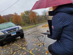
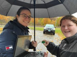
We received roughly the same results as with the first sensor. The range extended to about 11m. Interesting, accurate distance information was still returned after the car fell of the spectral line array, though only for about half a meter. As it was raining, this also allowed us to confirm that the operation of the sensor was not effected by precipitation (assuming the two sensors have the same clear weather range), though this was never expected to be a problem. We discussed trying to test the beamwidth of the sensor, but determined that though we were able to hold the sensor a certain distance away with insignificant error (1 or 2 cm over 1 or more meters) that even with a compass to determine angle, we could not hold the sensor at the correct angle. This testing will be preformed once the sensors are more securely on the mounts. Emily and I currently have plans to get together 21 NOV to preform mounted sensor testing with both sensors.
I also talked to Jason this week and took him through the interface for my code so that it could be integrated easily. I believe he now understands how to call the written functions on the data collected by the sensors. I also took some time to solder a few components for connections. I added the photoresistor to a circuit board with resistor and wiring for Emily so that she could use said setup to determine whether taillights would need to be on. I also started soldering some wires to male-to-male connector pins we are planning to use with the STM as they are still removable if necessary, but fit much more securely than wire alone.
Emily’s Status Update
We’ve switched to using 5V batteries which we got in this week. I didn’t realize that the Arduino can run off of 5V through the 5V or through the USB input. This will also double our battery capacity. I tested them, they run at the required voltage. I’ve gotten the LEDs and the Arduino to run off of the battery power. I still have to test the STM, but it worked with the 12V, so this should be alright as well. Next up with power is to run the sensors off of the STM.
Jason and I tried to get various communications methods working between the STM and the Arduino. I’ll be helping with that more actively next week.
I’ve started modifying the CAD for the final version of the mount. We changed how the batteries are going to be positioned relative to the bike, so the mount overall will be smaller now and I won’t have to print it in two pieces. I’m also planning on printing circular clips to hold the turn and power switches on the bike.
I also got our light sensing to work on the Arduino. We use it to inform whether the tail lights need to be on, and I’m going to change it to set the overall brightness for the handlebar LEDs as well (so they aren’t so blindly bright at night).
I did some testing with Albany on the other sensor a couple days ago, and we are going to meet up on Sunday to do testing with the two sensors together on the mount. We are also going to use this to test the angular response of the sensors.
I emailed DFRobot about the sensors. We aren’t seeing the range that we expect and their documentation is very limited and unclear, so hopefully they will get back to us soon. We are continuing to move ahead, but it would be nice to get some kind of answer to what we are seeing.