ECE 525
Cadence Tools Lab Manual
SIMULATION:
TOPICS:
Verilog Simulation
Spectre Simulation
VERILOG SIMULATION [TOP]
Verilog is used to do simple behavioral simulation of your design. The
verilog transistor model is an ideal switch. No electrical parameters are
used or considered in Verilog simulation. Verilog simulation is used to
quickly verify that your design behaves correctly.
Starting the Verilog Simulator
[TOP]
-
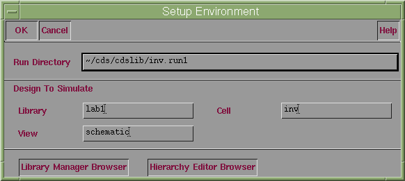
To start the Verilog simulator, select Tools...Simulation...Verilog-XL
from the Composer window of the schematic you wish to simulate. The Setup
Environment window will open:
-
A directory will be created to hold the simulation. You should put it in
your library directory ( ~/cds/cdslib/ ) and use the default directory
name, which will be cellname.run1, where cellname is the
name of the schematic you are simulating. In the example above, a cell
named inv is being simulated. The correct path for the run directory
is shown in the Run Directory box.
-
The default values for the Library, Cell, and View fields should correspond
to those of the schematic being simulated and should not need to be changed.
-
Click OK.
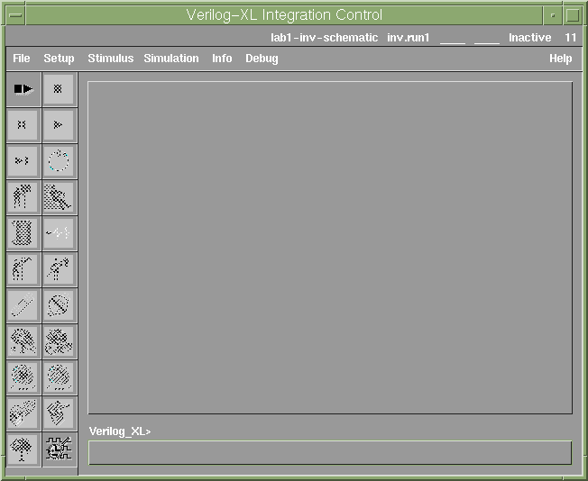
The Verilog-XL Integration Control Window will open, as shown below. This
is the main window used for all aspects of Verilog simulation.
Stimulus Files [TOP]
A stimulus file is simply a Verilog file that describes the inputs to
the circuit under test. You need to create a stimulus file for every design
that you wish to simulate. To create a stimulus file:
-
Select Stimulus...Verilog from the Verilog-XL Integration Control
window.
-
A dialog box will appear stating that "There is no test fixture file in
this run directory". Click Yes to create stimulus template file.
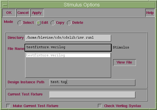
The Stimulation Options window will open:
-
Click on the Edit button and then select the file testfixture.verilog.
This is the name of a template file that Cadence has created based on the
input pins in your schematic.
-
Click OK. A text editor (emacs) will open with the stimulus file..
You should see your inputs defined in this file with the format: InputName
= 1'bo. This indicates that the input pin with the name InputName
is defined as a single bit number (1') with initial value a binary
0 (b0).
-
For the labs in this class, your stimulus files will only need to toggle
the inputs. To do this, add the following line to the very end of stimulus
file (after "end"):
always #20 InputName = ~InputName;
This tells the simulator that every 20 ns (#20), the input with
name InputName will be changed to its complement ~InputName.
If
you have more than one input, you will add a line like the one above for
each input. The time value for each input should be twice that of the next
least significant input. For instance, if you are testing a schematic with
four inputs I1, I2, I3, I4, where I1 is the LSB and
I4
is the MSB, you would add the following four lines:
always #20 I1 = ~I1;
always #40 I2 = ~I2;
always #80 I3 = ~I3;
always #160 I3 = ~I4;
-
Finally, a line must be added to tell the simulator when to stop. It should
be the last line in the file and will be of the form:
initial #320 $finish;
This tells the simulator to stop 320 ns (#320) after the simulation
starts. Your simulation should run for at least twice the value associated
with the MSB of your inputs. In the example above, I4 is the MSB
and its time value is 160 ns, so you would want to run your simulation
for at least 2 x 160 = 320 ns.
-
Save your simulation file (Ctrl-X,Ctrl-S) and then close the text
editor window (Ctrl-X,Ctrl-C)
Running the Verilog Simulator
[TOP]
-
Select Simulation...Start Interactive from the Verilog-XL Integration
Control window.
Important: If a dialog box appears asking if you would like
to re-netlist appears, answer No. Answering yes will overwrite all
of the editing of the stimulus file that you just did. If you have changed
your schematic, however, you will need to answer yes, so that the changes
will be included in a new netlist. Then you will need to go back and re-edit
the stimulus file.
-
It will take a little while for the interactive simulation mode to start.
Wait until you see the C1> prompt at the bottom of the Verilog-XL
Integration Control window before proceeding with the simulation.
-
Next you must tell the simulator which signals you wish to monitor. You
must specify all inputs and outputs that you wish to be displayed. Do this
by selecting Info...Monitor. from the Verilog-XL Integration Control
window menu. The Monitor window will open:

Enter the signal names into the Signal field and click OK.
-
To start the simulation, select Simulation...Step from the Verilog-XL
Integration Control window menu. The Step Form window will open:

Enter the number of ns for each step (20, as shown above should
be fine for your simulations in this class) in the Step Value field and
click OK.
-
The simulation will run and the values for the signals at each time step
will be shown in the Verilog-XL Integration Control window.
-
When you are done simulating, select File...Quit from the
Verilog-XL Integration Control window.
Waveform Viewing [TOP]
In addition to the text based output, the Verilog simulator can also
output waveforms. To create waveform output, start the Verilog simulator  and create a stimulus file
  as usual. Then you will setup the signals to be recorded and then view
the waveforms.
Setup
-
Start running the simulation by selecting Simulation...Start Interactive
from
the menu.
-
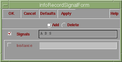
Select Info...Record Signals from the menu. The infoRecordSignalForm
dialog box will open:
-
Click in the check box to the left of the Signals field.
-
Enter the names of all of the signals that you wish to record in the Signals
field
and then click OK.
-
If you want to see the text output as well, enter the signals in the Info...Monitor
dialog
box also.
Viewing
-
Run the simulation as usual. Wait until the Verilog simulation is complete
before proceeding.
-
Select Debug...Utilities...View Waveform from the simulator menu.
This will start the Simwave program.
-
Select Tools...Browser from the Simwave menu.
-
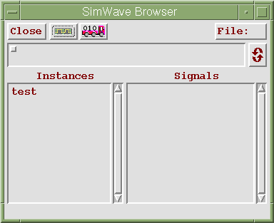
In the Simwave Browser window that opens, double-click on Test in the Instances
list.
-
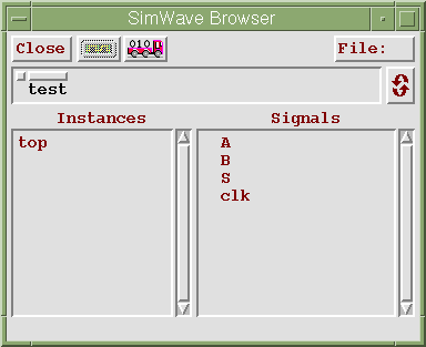
The signals that you selected to be recorded will appear in the Signals
list:
-
Highlight all of the signals and then click on the Display Signals
button (the button with the little square wave).
-
This should display all of the waveforms in the SimWave window.
-
To print the waveforms, select File...Print...
from the SimWave menu. This will allow you to create a PostScript file,
which you can send to the printer from the Unix command line, using the
lpr command.
SPECTRE SIMULATION
Spectre is used to do analog simulation of your design. It simulates
the behavior of your circuit at the device level and uses SPICE type component
models and equations to accurately determine determine behavior.
Setting Up to Run Spectre
[TOP]
-
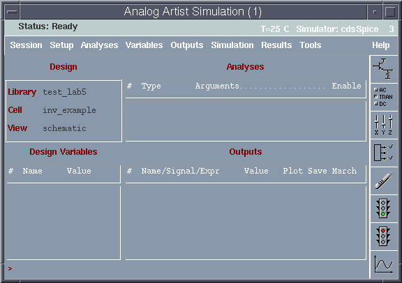
From the Composer schematic window, select Tools...Analog Artist. The
Analog Artist Simulation window will open:
-
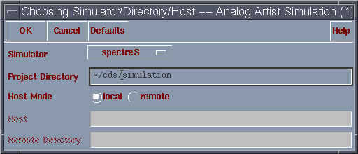
Select Setup...Simulator/Directory/Host from the menu. Set the Simulator
field to SpectreS and the project directory to a directory under
your~/cds directory ans click OK. Answer No when asked if you want
to save the current state.
-
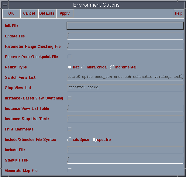
Select Setup...Environment from the menu. Set the Netlist Type
to flat, unless you are going to simulate a design with multiple
levels of abstraction (like an extracted layout netlist), in which case
choose hierarchical. Make sure the Include/Stimulus File Syntax
option is set to spectre and click OK.
Selecting Analyses
[TOP]
-
Select Analyses...Choose from the Analog Artist menu.

©
1999 Carnegie Mellon University


![]() and create a stimulus file
and create a stimulus file ![]() as usual. Then you will setup the signals to be recorded and then view
the waveforms.
as usual. Then you will setup the signals to be recorded and then view
the waveforms.


![]()