Steps:
Remove vdd line from the stimulus file
Adding vdd and gnd
Adding load capacitors
Add formula in Analog Artist
Basic Power Estimation[TOP]
Measuring the power consumed by your circuit is becoming essential in the design of modern IC's. It is no longer acceptable to make the design run as fast as possible and be as compact as possible in order to be considered a good design. Making the circuit consume very little power is also extremely necessary.
There are two modes in which a circuit can consume power: when the circuit is switching (inputs are changing and the outputs are changing to adjust to these new inputs); and when the circuit is static (inputs and outputs are NOT changing). Static power consumption used to not be a concern when most devices were plugged in all the time. For the few that weren't, people were glad to get an hour or two of use without having to plug in again.
To measure power in Cadence, you need to make only a few changes/additions to how you simulate your schematics and extracted view. The first change is to edit the stimulus file to remove the first line defining vdd since will be defined in the schematic. The second change will be to add vdd and ground to the schematic that you use to simulate your circuit. Then you'll place grounded load capacitors on your output. Finally, the last change you need to do is add another signal (actually, a formula) to be viewed.
Remove vdd line from stimulus file[TOP]
Remove the following line from your stimulus file:
vdd [#vdd!] [#gnd!] dc 1.8v
If the old stimulus file looks like this:
vdd [#vdd!] [#gnd!] dc 1.8v
VR  [#R]  [#gnd!]  PWL( &
 0      0  &
 0.1*t    0  &
 0.1*t+0.5n    1.8  &
 0.9*t    1.8  &
 0.9*t+0.5n    0  &
)
VS  [#S]  [#gnd!]  PWL( &
 0      0  &
 6*t    0  &
 6*t+0.5n    1.8  &
 10*t    1.8  &
 10*t+0.5n    0  &
)
The stimulus file should now look like this:
VR  [#R]  [#gnd!]  PWL( &
 0      0  &
 0.1*t    0  &
 0.1*t+0.5n    1.8  &
 0.9*t    1.8  &
 0.9*t+0.5n    0  &
)
VS  [#S]  [#gnd!]  PWL( &
 0      0  &
 6*t    0  &
 6*t+0.5n    1.8  &
 10*t    1.8  &
 10*t+0.5n    0  &
)
Adding vdd and gnd[TOP]
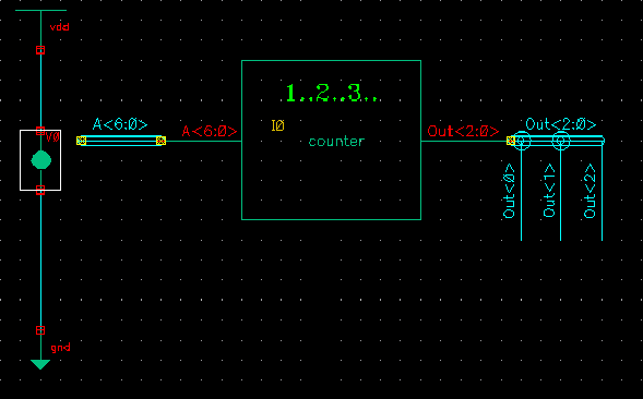
Instead of adding two floating wires to the schematic you are simulating and labeling them vdd! and gnd!, you should now add a vdd symbol from the NCSU_Analog_Parts library and a gnd symbol from the same library. Now place a vdc symbol between them, wire gnd to the bottom terminal of vdc and wire vdd to the top terminal of vdc. Select the vdc symbol and hit "q" to get the properties window. Edit the DC voltage so that it is 1.8 V
Your schematic should look like this:

Add load capacitors[TOP]
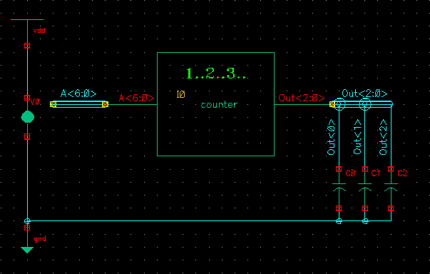
Now for all your outputs, attach a 5 fF capacitor as a load for it to drive. You can find capacitors in the NCSU_Analog_Parts library just like you did for vdd and gnd. You may need to add single bit wires with labels to your multi-bit buses as shown above. The capacitors should then be wired to gnd as shown in the picture below.
Add formula in Analog Artist[TOP]
In addition to selecting the signals you want to see in your waveform, you need to add a formula to calculate your circuit's power consumption. To do this, go to the Analog Artist window.
(Analog Environment Simulation Window) Tools -> Calculator ...
(Calculator)
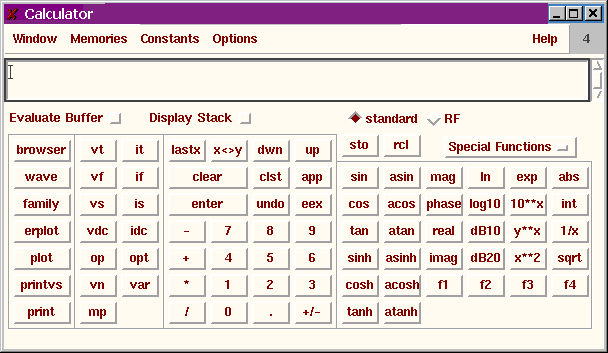
- Click vt (top button in the second column)
- Click the wire between the vdd and vdc symbols in your schematic
- Click it (top button in the third column
- Click the top pin on the vdc that you added to your schematic
- Click the * button (multiplication)
- Click Special Functions
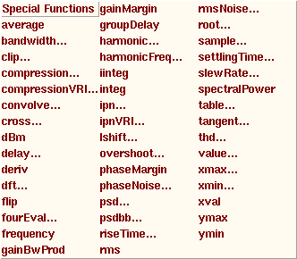
- Click integ (NOT iinteg)
- The "Definite Integral" window pops up
- You should enter 0 for the "Initial Value" and the length of your simulation for the "Final Value"
- You can use different numbers if there is a particular transition you're interested in measuring
- Click OK to close the "Definite Integral" window
- Click abs (top right button on the calculator)
- Click enter (rectangular button under clear towards the center)
- Enter the amount of time you used for the integration command ("Final Time" - "Initial Time")
- Pay attention to units here. You can use the keyboard to type "n" for nano, "p" for pico, etc., instead of using the gui.
- Click the / button (division)
- You should see something like this in the calculator window:
abs(integ(IT("/V0/PLUS")*VT("/vdd!"),0,2n))/2n
where 0,2n is my integration range and 2n is the length of the range
- Another example:
abs(integ(IT("/V0/PLUS")*VT("/vdd!"),1n,3.5n))/2.5n
gives you the power consumed between 1n and 3.5n from the start of your simulation
Leave the Calculator open and go to the Analog Artist Window again.
(Analog Environment Simulation Window) Outputs -> Setup ...
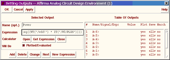
- Name (opt.) Power
- Click Get Expression (this will fill in the Expression field)
- Click Add
- Click OK
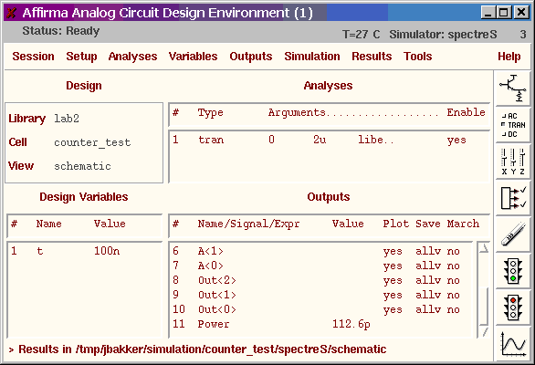
THAT'S IT! Now run your simulation like usual. The power consumed by
your circuit will be displayed as a number in your Analog Artist
window. For example, the power consumed in this example was 112.6pW.
![]()