Towers of
Final report
16-778/18-578/24-778
Mechatronic Design
Spring 2007
Team H: Team Joe
Joseph Chang
Nicholas K. Rubi
Pavinee Hassavayukul
Abstract:
We have developed a mechatronic
system to solve the famous
1. System Overview
This year’s mechatronic design project was ‘Towers of Hanoi
Solver.’ The towers of

![]()


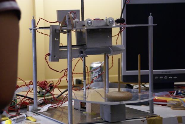
Figure 1.1 This shows the overall system
The system consists of 3 main components, as shown in figure 1.1. They are the turntable subsystem, elevator subsystem, and gripper subsystem. The gripper subsystem’s objective is to grab a disk and hold it in place. The elevator subsystem then raises and lowers the gripped disk to the desired height. Finally, the turntable subsystem rotates the gripper so that target peg can align with position of gripper. We used push buttons for the system’s sensors. All subsystems should coordinate together to complete the project objective.
1.1 Desired functionality
The goal of this project is to build the
1. Mechanical subsystem: it should be able to pick up and releases the disks. Then, it will move the disk to its destination peg. The mechanical subsystem should also be robust. Furthermore, the drive mechanism and motors should provide a sufficient amount of torque with a shortest amount of time.
2. Sensor subsystem: it should be able to identify the type of the disks in the peg. Additionally, it should be able to measure the positions that our mechanisms.
3. Software:
it should be able to solve the
4. Circuit: it should be built to input and output the correct voltages to and from the PIC. Besides that, it should be neat and clean.
5. Power supply: it is needed to provide the right amount of current and voltage to the circuit.
With all of the above required functionalities, our system
will be able to solve the
2. System
With the consideration of the goal and the desired functionalities, we have designed the following systems. Figure ... shows the system block diagram.
Figure 2 System block diagram
2.1 Mechanical System
There are three main mechanical subsystems: turntable, gripper and elevator unit.
2.1.1 Turntable Subsystem
Turntable subsystem is where 3 pegs are located. Circular base will be rotated by a servo motor. Our prototype design had a DC motor with gearbox attached. Our original plan was using encoder to control the turntable. When we made our first turntable subsystem, we chose gear ratio of 1:6. The gear ratio didn’t reduce the speed enough, thus encoder couldn’t provide enough precision. The servo motor provided relatively easier control and simpler mechanism. It also provided enough precision.
The only disadvantage of having a servo motor as an actuator for the turntable subsystem was limited angle of operation. Operation range of the servo motor was little over 180 degrees. Bigger size of rotating base was needed due to limited angle of operation, since gripper subsystem should not hit any other pegs or discs.
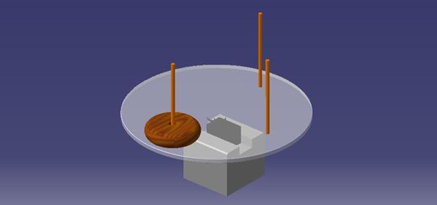
Figure 2.1.1 Turntable
2.1.2 Gripper Subsystem
1.
Gripper Subsystem

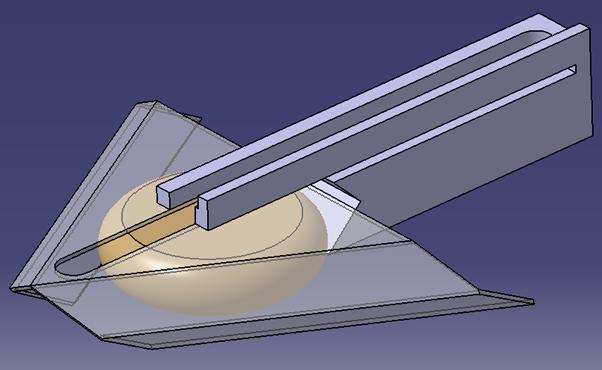
Figure 2.1.2.1 Final Design of Gripper Subsystem
The main task of the gripper subsystem is grabbing disc in place. Our gripper design has a unique design. We have 6 kinds of discs to grab, and they all have different radius, height and curvature. We wanted our gripper design to be fully capable of grabbing all 6 different discs. Other goal of the gripper system was to avoid wobbling motion while the disc is at grabbed state. In order to do that, the gripper was required to have at least 3 points of contact, with each contact point being 120 degrees apart from each other.
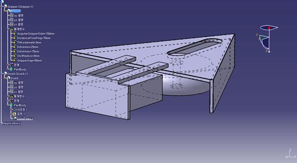
Figure 2.1.2.2 Prototype Design
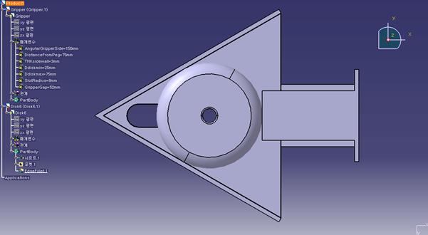
Figure 2.1.2.3 Points of Contact
This is how
our first design of the gripper looks like. It has 3 points of contacts between
the gripper subsystem and a disc. A rectangular block on the right side of the
picture is a clamp that opens and closes the gripper. Also there is an
elongated hole on top of the triangular gripper piece. This elongated hole is a
clearance hole for a peg to go through during operation of


![]()


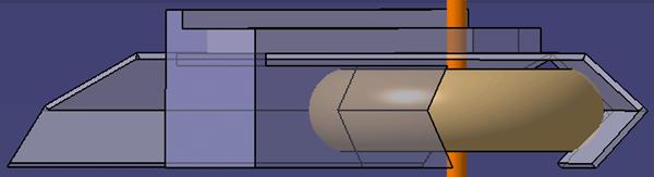
Figure 2.1.2.4 6 Points of Contact
The main difference between the final design and the prototype design is a presence of v-block feature. V-block features are located at interior walls of gripper and also at the clamp. V-block increased number of contact points. There are 6 points of contact in the final design, making grabbing more stable than the prototype design. There is another advantage of having v-blocks. When grabbing discs, the target disc will be centered automatically, no matter how big the disc is.
Figure
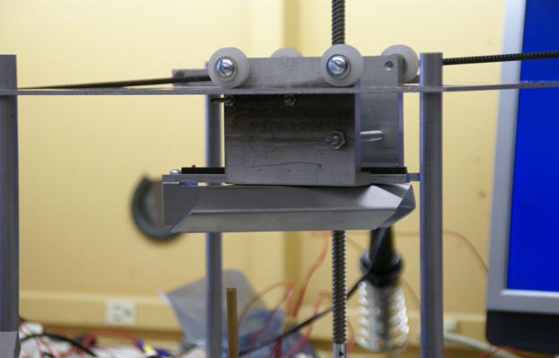
2.1.2.5 Real picture of gripper
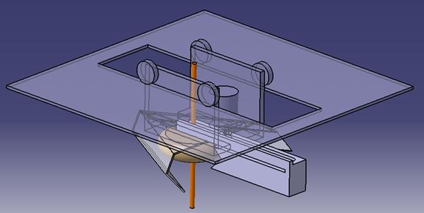
Figure 2.1.2.6 Gripper holding disk
The gripper subsystem has 2 degrees of freedom. Two JAMECO gear-head motors were used. These motors have integrated gearboxes with 1:50 gear ratio. Both motors use rack-and-pinion system to transmit motion. One motor actuates the clamp to open and close. The other motor actuates whole gripper system to slide horizontally. Horizontal motion of whole system is required because position of target peg depends on the size of target disc.
2.1.3 Elevator Subsystem
The elevator subsystem translates top plate vertically. Objective of the elevator subsystem is to move the gripper subsystem, which is attached to the top plate, to desired height. One JAMECO gear-head motor with gear ratio of 1:60 was used. A Lead screw was used for power transmission. Lead screw was chosen to prevent backlashes, since the lead screw is not back-drivable. This sub-system requires the most torque among 3 sub-systems because the top plate has to move with heavy gripper subsystem attached.
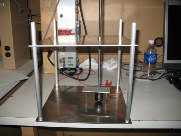
Figure 2.1.3.1 Elevator subsystem
2.2 Electrical System
The task for the electrical subsystem is to provide the interconnection between the mechanical subsystem and the software. Thus, the circuits are needed to be built such that it will provide correct voltages and currents to the motors and the PIC.
In the initial design, the sensors that we used are the encoders and the SHARP IR detector. The encoder would accurately measure the position that the turntable rotated, the height of the raising unit and the distance that the gripper moved. The use of encoder will allow us to have a feedback control, using PIC controllers. As a result, we can accurately pick up and release the disks. However, due to the integration problem, which we will elaborate in the result section, we decided to eliminate the use of encoders and changed the type of motor for the rotating unit. Additionally, to identify the types of disks in the starting peg, the SHARP detector was used. However, toward the end of the class, it got broken. Hence, this led to the decision of using only the buttons as our sensors. Therefore, the current circuit that we use consists of the PIC board and the motor board. Although the current circuit doesn't have the encoder and the IR detector circuits, they will be presented for a completeness sake. As a result, in this section, we will illustrate the circuit in the PIC board, the motor driver circuit and the encoder circuit.
2.2.1 PIC board
The PIC board consists of the PIC microcontroller, its circuit, and the button circuit. The PIC circuit consists of a crystal, capacitors, resistor, voltage regulator, and the dual drives/ receiver (MAX232). It also contains the connectors to other electrical subsystems such as the motor drive board and RC servomotor. The PIC outputs the voltages to the motors and inputs the voltages from the buttons, which is our sensor in this case. The circuit for the buttons are built on the PIC board. It consists of a SPST button and a 128K resistor. Its schematic is shown in figure 2.2.1.1. This board is powered by 12V from the power supply. The board layout is shown in figure 2.2.1.2.


Figure 2.2.1.1 Schematic for
the button where R = 128K Ω.
![]()
Figure 2.2.1.2
PIC board layout
![]()
![]()
2.2.2 Motor
Drive Board
The motor drive board is used to
control the DC voltage applied to the motor. It basically acts like switches.
This will allow us to drive the motor forward or backward with the amount of
voltage inputted. The circuit consists of the diodes, the capacitors, the
voltage regulator (LM340L), the driver IC (L298N) and the dual row header. To
connect the motor drive board and the PIC board, we use D-sub connectors. The
board outputs the voltages to the motor via pin motor+ and motor-.
2.2.3 Encoder
Board
The encoder
board is used to output high or low signals to the PIC microcontroller. They
consist of two resistors and the OMRON 1042 slot encoder. The resistors are
1000 and 120 Ohm, which are the values that we found to be able to output the
right amount of voltages. This board is
powered by 5V inputted from the PIC board. The schematic for the circuit of the
encoder is illustrated in figure 2.2.3.1.


Figure
2.2.3.1 Schematic the
encoder where Rf = 120 Ω and RL = 1000 Ω
Earlier
on in the course, we also use IR detector to identify the type of disks in the
starting peg. The IR detector has to be powered by 5V and it outputs the analog
signal (0-5 V) which increases as the distance from the object to the sensor
increases.
Furthermore,
to keep our circuit neat and clean, we use connectors to connect the wires
between the PIC board and other electrical breakout boards.
2.3 Software
Our code consists of two components: there is a Matlab graphical
user interface (GUI), which takes user inputs, and microcontroller code, which
controls the motors and sensors. Below are flowcharts describing the software
in both systems. There is also a picture of the Matlab GUI, below.
2.3.1 Matlab
Code
Matlab GUIs consist of a .m and a .fig file. The .m file contains the code while the .fig file contains the location of each component. Refer to figure 2.3.1.1 below to get an idea of where the .fig places everything. Figure 2.3.1.2 shows the flowchart of GUI operation. The first function of our .m file is the GUI_OpeningFcn(), which draws the GUI, sets up the serial_waiting function to be called when data is received over the serial port, and sets up the handles structure, which is how data is stored in the GUI. The rest of the code is primarily composed of callback functions, which are triggered when user inputs are detected in their specific area. Each GUI element (button groups, buttons, listbox, etc) has its own callback, and the tasks that we assigned to each are displayed in the flowchart. Including delays in the transmission system was necessary because the PIC and Matlab would try to send messages when they hadn’t finished transmitting their last message. This would cause the PIC’s port to become disabled. The serial_waiting interrupt is responsible for parsing messages from the PIC. It then updates the drawing based on the data or displays new information in the status box. The picture in the GUI was created from many different shapes, overlaid on a plot with ‘holding’ enabled. The picture can thus be updated by enabling or displaying each call function, and transmitting a different rotation and translation to each piece.
Figure 2.3.1.1 The
Matlab GUI obtains the source peg, destination peg, and number of disks from
the user. It also displays status updates from the PIC, and has the capability
to refresh it’s drawing using information received from the PIC.
Figure 2.3.1.2 This flowchart shows the operation of the gui .m file.
GUI_OpenFcn() sets up the system when the GUI is first opened, serial_waiting
is an interrupt that is called when data is received over the serial line, and
the rest of the functions serve as callbacks for when user clicks are detected
within their areas.
2.3.2 Microcontroller Code
At the top of the code are arrays
disks_1, disks_2, etc that have the sequence of moves to complete the algorithm
for source peg 1 and destination peg 3. The function disks2pegs reads the next
move from the algorithm array, then calls the move function with the source and
destination altered to use the real current source and destination, which may
not be 1 and 3. The original intention was to use recursion, but the compiler
did not support it. Since we already implemented and tested the algorithm in
Matlab, we chose to hardcode the moves for each disk number case, so this is
where the disks_# arrays come from.
The system begins moving when the
PIC receives the ‘go’ signal from the Matlab GUI. If it gets other signals
(change in source peg, destination peg, or number of disks) then it alters the
global variables storing that information. The algorithm then reads each line
of the appropriate disks_#, translates the move directions for the current
source and destination peg, and calls the move function, which powers the
motor. This is demonstrated in the flowchart below.
End of Array![]()
3. Parts List
|
Part |
Brand |
Model |
Description |
Quantity |
Cost (each) |
|
Push Button |
Unknown |
Unknown |
SPST. Found in the lab |
4 |
$0.69 |
|
Motors |
Jameco |
161381 |
Two for the gripper and another for the raising unit. Found in the lab |
3 |
$22.49 |
|
RC motor |
Hitec |
HS311 |
Standard RC servo |
1 |
$8.99 |
|
IR sensor |
Sharp |
GP2D120 |
For identifying the disks |
1 |
$17.18 |
|
PIC board |
Microchip |
18F4431 |
Consisted of the board and PIC microcontroller. Found in the lab. |
1 |
~ $13 |
|
Motor Driver |
- |
- |
Built ourselves from spec. Regulates power. |
2 |
~ $5 |
|
Resistors |
- |
- |
128K |
4 |
~ $0.10 |
|
Wires + connections |
Unknown |
Unknown |
For the connection |
1 |
~ $20 |
|
Aluminum |
- |
6750K161, 8973K86, 5865T32 |
Aluminum for mechanical construction |
1 |
$60.01 |
|
Nut |
- |
95072A125 |
Bronze Precision Acme Round Nut 2 Turns per inch, 3/8” – 8 size, 4 starts. and Bore |
1 |
$29.87 |
|
Lead Screw |
- |
- |
2 rotation/in |
1 |
$30.00 |
|
Gears and Rack |
- |
6295K11, 6325K89 |
Made of steel |
1 |
$43.20 |
|
Glue |
- |
- |
For fastening |
1 |
$10 |
|
Assorted screw |
- |
- |
Found in the lab |
1 |
~$5 |
|
Cardboard for mounting circuit boards |
- |
- |
Found in the lab |
1 |
~$2 |
|
Computer power supply |
EMACS |
HP2-6460P |
Used and found in Wean Hall |
1 |
~$20 |
|
Plexiglass |
- |
- |
Material for rotating base |
1 |
$5 |
|
Balsa Wood |
- |
- |
For mock-up |
1 |
$23.43 |
|
Transparency |
|
- |
For encoder strips |
1 |
$12.95 |
|
Total
Cost |
$381.26 |
||||
Table 1. Parts list
The most expensive single item was
aluminum, followed by our rack for gear trains. Each of the DC motors was
around $23 so with 3 motors, this was also a major expense (~$67). Finally, the
lead screw and the nut it requires were each $30, making that complete system
cost $60. Luckily, the motors and many of the mechanical parts we were able to
get and share with other groups. However, we still spent $204 so we expect to
be reimbursed for the full $200.
4. Results
One of the first steps to
implementing the system was to create the turntable. To fully control the speed
and position of the RC motor, we implemented our own pulsing function, which
allowed us to use any output pin. Once the mechanical systems were complete, we
were able to use trial and error to ensure that each of the pegs spun to the
perfect centered position for the gripper.
Next, we attempted to create our own
encoders. Using one infrared photo detector, we found that the motors did not
instantly stop or change direction. Also, when the photo detector was on the
edge of a new reading, it would often report several readings when the system
was not really moving. This led us to use two photo detectors, which would
allow us to know direction and if the system was really moving. The problem at
this point was that most interrupts were rising or falling edge, but not both.
This meant that we would miss many encoder level changes because we would not
have enough interrupts that could read rising and falling edges for our motors.
As a result, we decided to move to an infrared sensor system to detect when we
were at the correct height and approximately what disk we need to grip.
The infrared system worked
relatively well. In figure 4.1 we show the results of panning across 6 disks.
Using the infrared sensor would allow us to determine when a disk is at the
correct height to be gripped. It would also allow us to get a good idea of
which disk (large or small) we were detecting. Unfortunately, near the end of
our project, our infrared sensor stopped working and we are not sure of the
cause. At that point, ordering another sensor would have been hard on our
budget and would have required a lot of scrambling to get properly implemented.
As a result, we tried to use a button system. Buttons were already available
and free from the Carnegie Mellon Tech Electronics store.
Figure 4.1 This chart shows the analog readings for the
infrared sensor being panned across 6 disks. The largest disk is clearly
visible at the 200th reading, and the next 4 as well. The sensor is
unable to see the difference between the smallest two disks, but it is clearly
different from reading nothing, as seen at around the 50th reading.
The buttons allowed us to have
reference points so that when we operated the motors at a certain duty cycle
for a particular length of time, we would know where they were at.
Unfortunately, inconsistencies in the amount of resistance the motors had to
overcome made this system unreliable. Also, the amount of torque a motor
produces is proportional to the current it receives. To ensure consistent
current, we had to stop using batteries and switched to a computer power
supply.
We never found a clear solution for keeping the disk still while we
gripped it, as we were not even sure which disk we were gripping and how far
the motors should move. As a result, when we needed to drop a disk, the center
of the disk was not always aligned with the center of the peg that it needed to
drop onto. A solution that we developed was to lower the disk near the peg,
loosen the grip on the disk, and twitch the turntable until the disk fell onto
the peg. This process could be tuned to work with some of the disks, but without
knowing which disk we were actually holding, it was impossible to get it
working for disks of all sizes. When the other systems were working, we could
expect this to work around 75% of the time for the largest two disks, around
50% of the time for the third largest disk, and very rarely for the other
disks, without tuning it for them (which would then prevent it from working for
the larger disks).
The buttons worked as expected, except for a floating voltage problem. The buttons were initially attached to a 5V supply on one end, and an input to the PIC on the other. When the button was pressed (for instance when the gripper was opened all the way), the input on the PIC would read 5V. When it was not pressed, it should read 0V. However, if we did not place a grounded resistor between the button and the input, a voltage could linger on the input line as nothing grounded it. Luckily, we thought of grounding the button with the resistor quickly.
The
overall system was pretty slow. The rotating turntable base was the fastest
component, and could rotate to any position in under a second. Each of the
components for the gripper took 1-2 seconds each at 67% duty cycle. Running
them at a higher duty cycle with open loop control would be so fast as to
potentially damage the system, so that speed was chosen. The gripper pieces
were typically moved at the same time. The lead screw took around 14 seconds
going from the turntable to the top of its range without a load, around 18 with
a disk, and 8 seconds going down. A complete pickup and placement would take
around 35 seconds. The heavy load and high friction that the lead screw had to
overcome were the main factors slowing it down.
5.
Conclusions
Our group placed emphasis on the
wrong elements of design. A great deal of importance was placed on being able
to securely hold the disks, so a unique gripper was designed. When it worked,
our gripper would very securely hold disks. However, the triangle shape meant
that the gripper held each disk in a slightly different way, which complicated
lifting and dropping disks. A simpler system, such as squeezing the sides of
disks between two straight pieces or lifting disks by sliding a flat surface
like a spatula underneath, probably would have been effective enough for this task
and would have considerably simplified the process. A lighter lifting system
also would have decreased the load on our lead screw and have lessened warping.
Another mechanical philosophy that
we embraced was flexibility, which worked to decrease our accuracy. Motors were
mounted in a way that would allow their easy removal in case we need to change
our design, but this often lead them to lose contact with the gear trains that
they needed to turn. The effects of friction that the motors had to overcome were
also inconsistent. When we switched to an open loop design because of our
difficulties with our home made encoders and our infrared sensor failing, our
system performed poorly because of mechanical inaccuracies. We should have
purchased encoders to improve our accuracy and reordered an infrared sensor
when ours failed, rather than try a button based approach to enable open loop
control with minimal feedback
Finally, the final design of our
system, with motors and enlarged top lifting surface, was not tested in CAD
software. This would have shown us clearance issues that we had to fix once the
mechanical systems were complete. These included motors and the enlarged
surface preventing the system from fully descending by not proving holes for
the pegs to ‘rise’ through. In all, implementing our system with the final
design was borderline impossible. We should have used a design with more
consistency and sensing to achieve success.
If we were redesigning the system
from scratch, we would definitely keep the RC servo motor turntable idea
because it worked very accurately and reliably. However, the gripping and
lifting subsystems had problems. To improve the gripping ability, we would
probably move to a simpler system that would squeeze the disks from the side.
This would ensure that the center was always in the same place, which would
simplify lifting and dropping the pieces. We could also use a “guide peg” above
the turntable’s pegs, to ensure that the disk is held steady while the
turntable moves.
This smaller and simpler gripper
would be significantly lighter than our current design. As a result, our lead
screw should move more quickly. We could also use a more powerful motor to move
our lead screw even faster. We would also purchase high quality encoders or use
stepper motors so that we always know where our subsystems are at. Finally, we
would use an infrared sensor to detect when the gripper is ready to grab a
disk.
However, to truly make this mass marketable, we think that a startup’s product would need to fulfill the following specifications:
· Cost less than $100.
· Solve up to 6 disks.
· Contain no loose or sharp parts.
· Detect when the system is not properly configured at startup (i.e. having all of the disks on the first peg at startup).
· Use different size and color disks.
· Be self-contained, neat, and robust
· Weighs less than 10 lbs.
· Measure less than 12in x 12in x 12in.
· Wall-powered
· Takes less than 5 seconds per move. So in order to solve six disks problem, it will take around 5.3 minutes.
· Smooth and noiseless except for cool ‘wooshing’ sounds.
· Use a LCD display and buttons or knobs rather than a laptop
Most of these requirements can be met using the design we developed for starting from scratch. However, the $100 cost would be hard to meet. To approach that requirement, wholesale prices would be needed, and that still might not be enough. The motors would also need to be very quick to achieve the speed necessary. Below is an image of what this system might look like. It would be very efficient and about as cheap as we believe this task can be completed with current technology.
Guide Rod
![]()
![]()
![]()
![]()
![]()
![]()
![]()
![]()
![]()
![]()
Figure 4.2 The user would hit
the red buttons to change the source peg, destination peg, number of disks,
start, and stop the system. The display would update to reflect the source,
destination, and number of disks currently selected. Hitting a button would
increment each category respectively. An RC servo motor would turn the pegs to
place them under the gripper. The gripper would then descend as a DC motor
turns the lead screw, causing the infrared detector to detect a disk. At that
point, the other DC motor would close the gripper. Finally, the gripper will
lift the disk onto the guide rod, the turntable will spin, and the gripper will
release the disk onto the destination peg.