Progress
February 28, 2017
After carefully soldering wires onto the tiny SMD pads of the Grid-EYE, we were able to communicate with the device over I2C and capture some live data. The gif to the left shows one person walking back and forth under the sensor while it was held 8 feet off of the ground.
This is a promising start - we're now confident that we can determine direction as well as differentiate between multiple people entering/exiting at the same time.
March 1, 2017
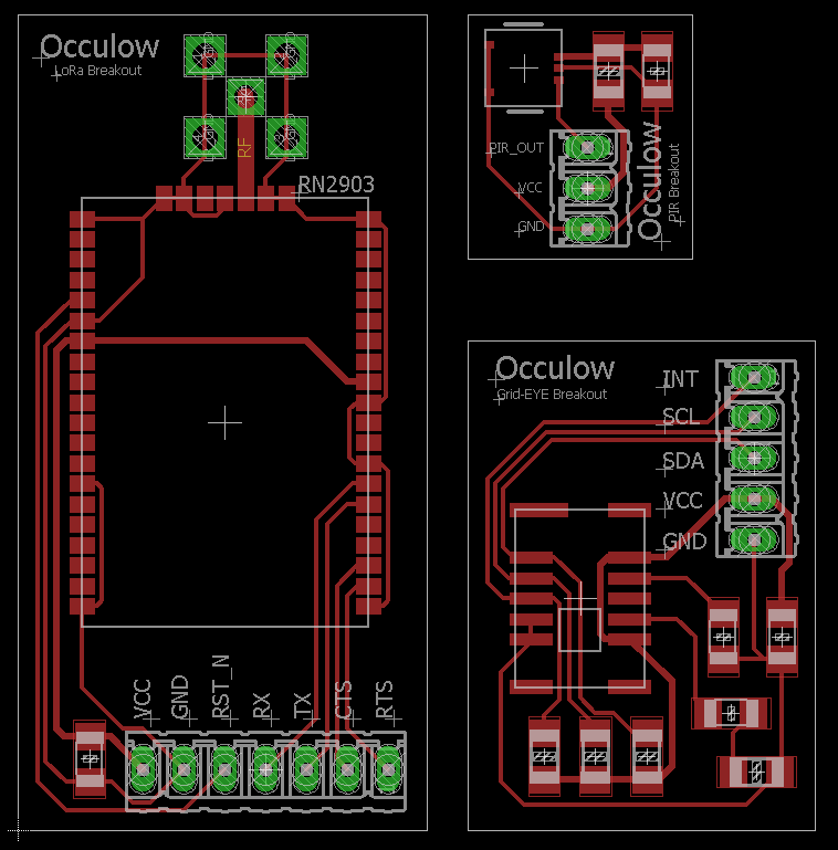
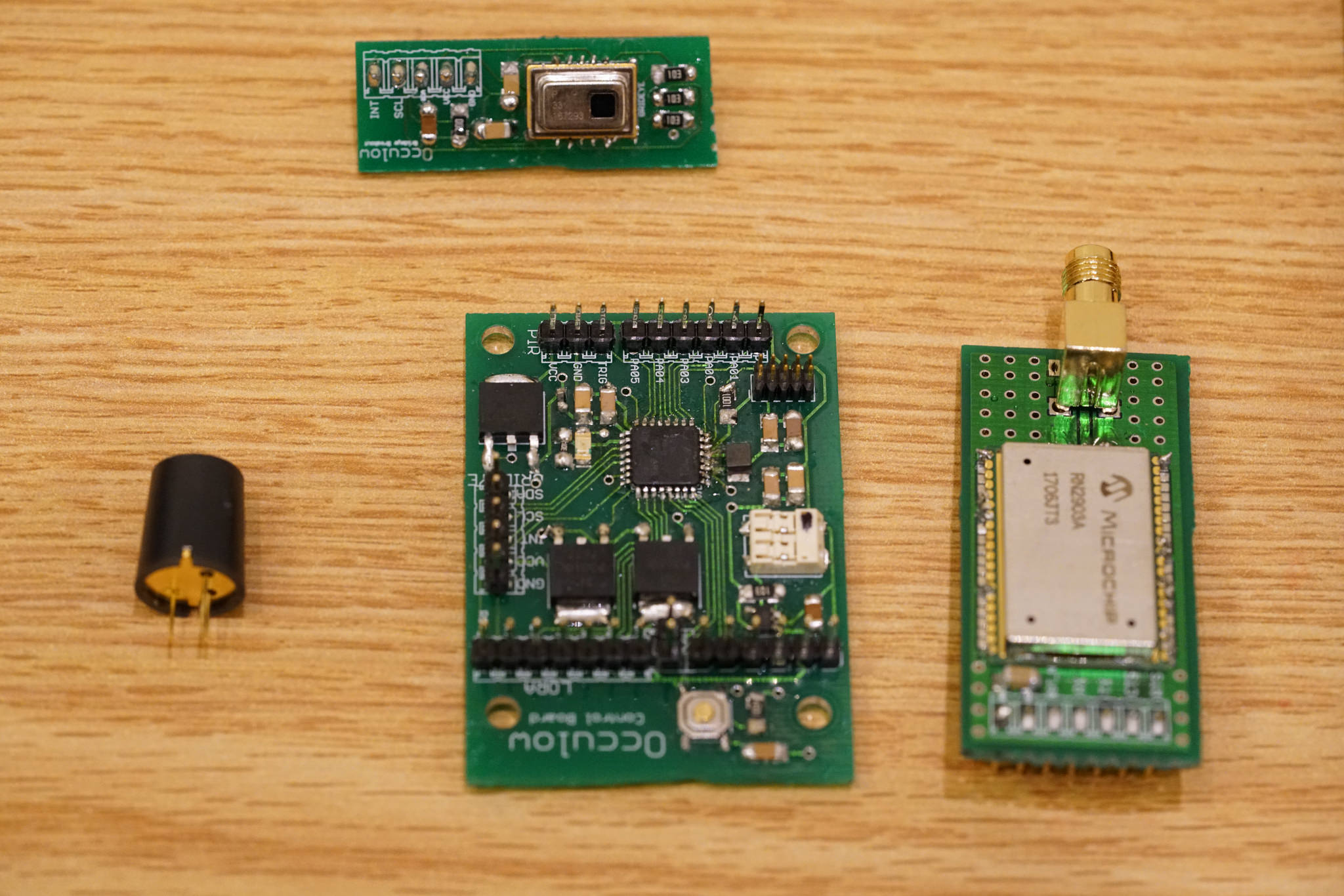
In the interest of rapid prototyping, we designed small breakout boards for each of our three major devices: the PIR motion detector, the Grid-EYE, and the RN2903 LoRaWAN module. The boards will be panelized so that we can break them apart and position them individually.
Each board is the simplest possible circuit to control the device, with control/output pins routed to GPIO headers. Each board also needs to be supplied separate power and ground.
March 18, 2017
Driving the RN2903 module from a Particle Photon we successfully connected to the LoRaWAN network and were able to publish data messages.
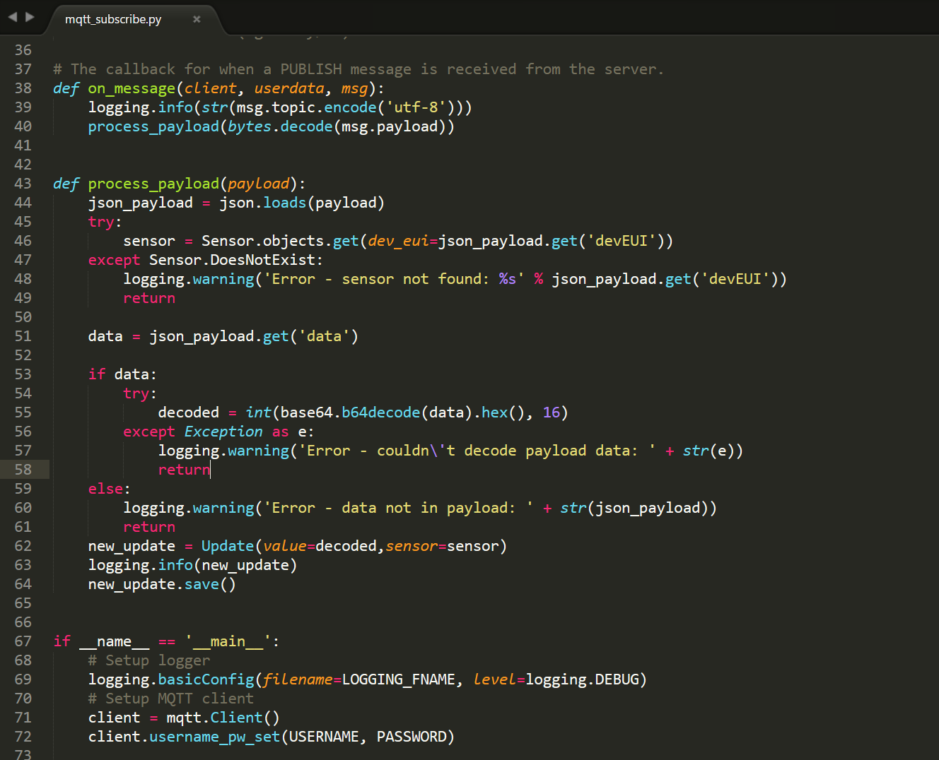
We also implemented an MQTT daemon process on our webserver that subscribes to the RX queue, receives messages from our device, and updates the database. These updates are shown in real time in a simple React-based frontend interface.
March 22, 2017
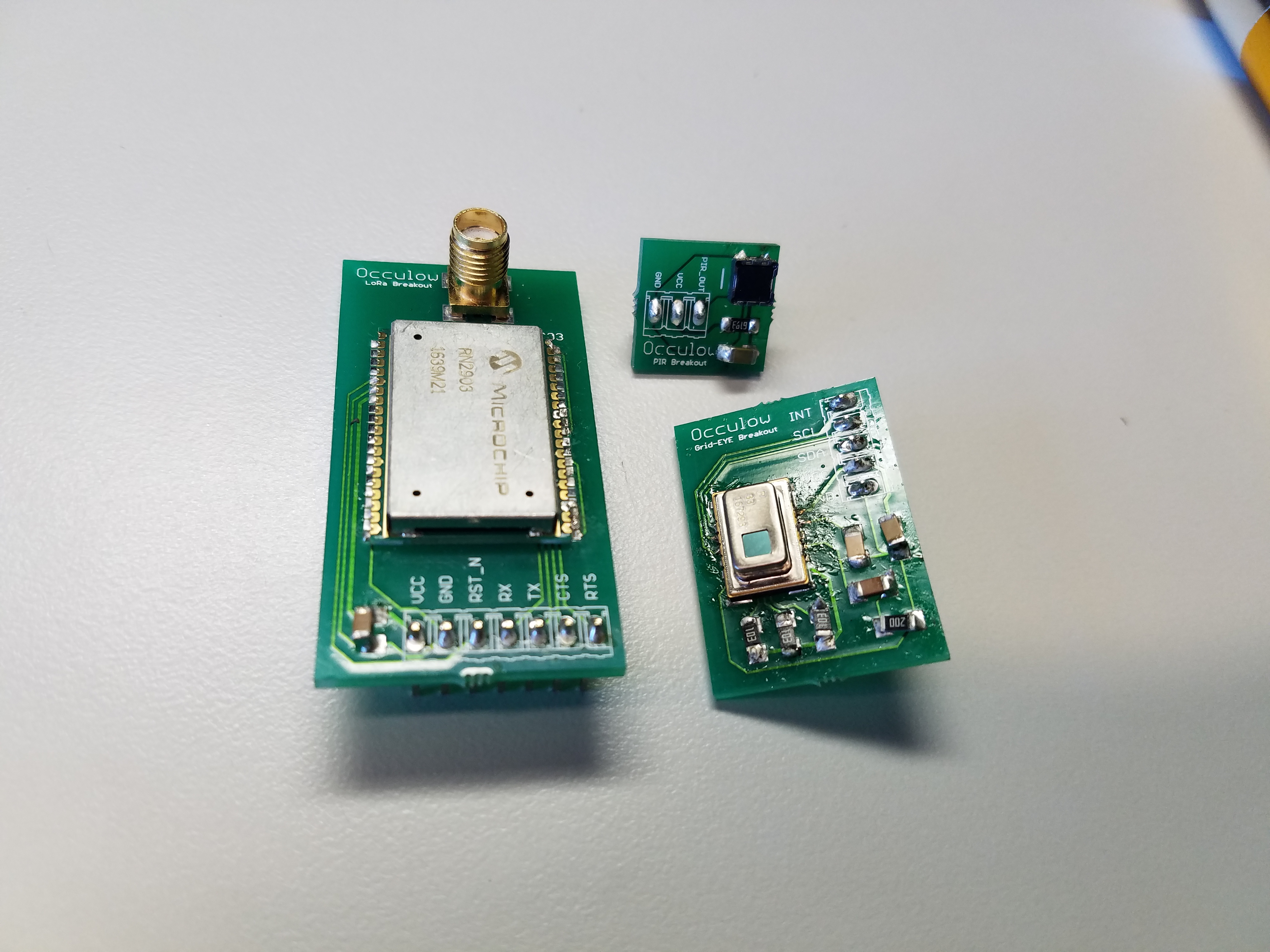
A long wait for parts delayed the final breakout boards, but we were finally able to complete each pcb with parts. Each component works as intended, and the small boards allow us to easily test multiple configurations.
March 31, 2017
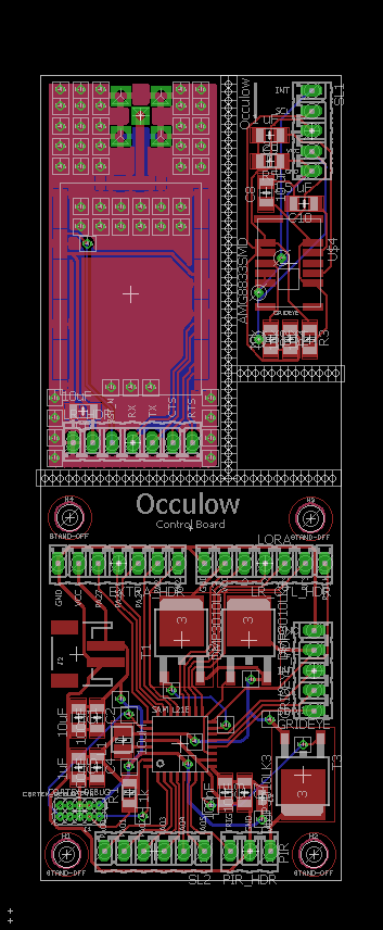
Pictured here is our semi-final PCB design, integrating the SAM L21E MCU and the RN2903/GridEye breakouts. As with the previous print, these are 3 separate boards panelized together into the same print job. The RN2903 and GridEye breakouts are essentially the same, with the only functional change being the addition of large ground planes and through-hole vias in order to provide shielding for the RF components of the LoRa module.
The control board features the SAM L21E microcontroller and headers to connect each of the different sensor components by wire. We chose to keep the sensors on separate boards to allow for easy placement and configuration in our final housing. A key feature is that we do not route the 3.3V power lines directly to the headers - instead, power to each breakout module is controlled by a switching transistor through the MCU. This allows us to completely shut off power to all components.
April 14, 2017
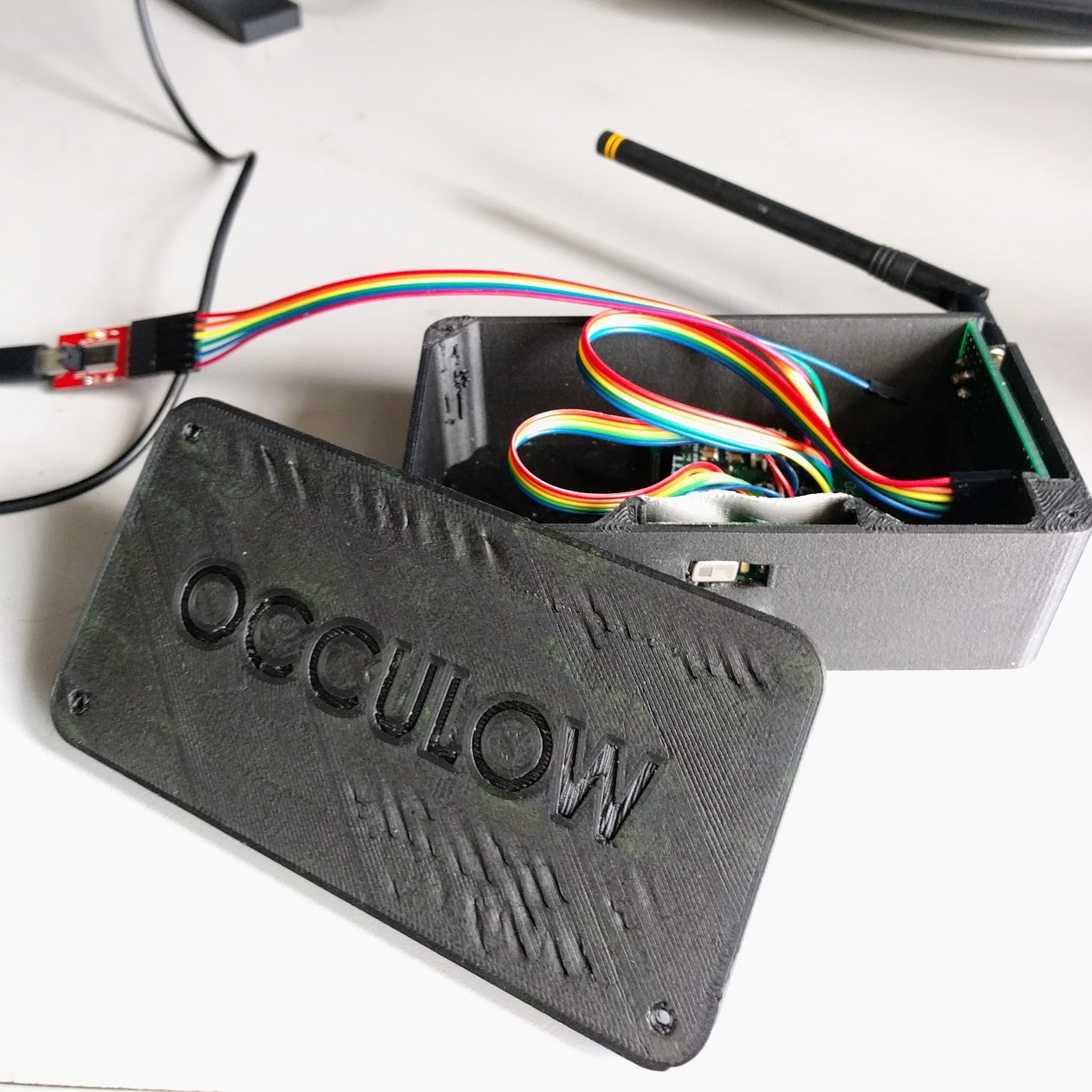
We finally got around to designing a case for our product! It's a rough print and certainly a draft design, but is able to houses all of our components and mount above a door frame. Additionally, we've integrated the full processing pipeline: from getting GridEYE frames to sending counts via LoRaWAN. The software for counting still needs to be tweaked for people counting and sleep2wake via the PIR sensor.
We're currently in the process of fixing the PCB design from last update to account for the small errors we made. A slimmer case is also in the works to give all the components a more snug fit and also add slots for a battery pack, indicator LED and power switch.
April 31, 2017
After one final PCB print run, we completed all of the control and sensor boards. Minor changes were made to the control board, including a dedicated FTDI header, LED indicator, reset button, and a 3.0V LDO voltage regulator in order to account for battery voltage dropoff. We also fixed an error we had in our power domain, where we were suppling power to the transistors from an invalid internal MCU supply.
May 8, 2017
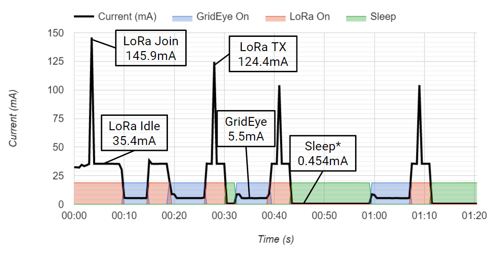
We made use of the power analyzer one final time to capture an energy usage trace of our final product. As expected, our sleep current is around 0.5 mA and the GridEye active current is approximately 5.5 mA. We suspect there are firmware bugs inside of the RN2903 LoRaWAN chip, as we were observing extremely high idle/sleep current draws - on the order of 40 mA, when we are expecting no more than 2 mA for idle and 100 uA for sleep. We resolved this issue by power-gating the RN2903 chip completely. The lifetime of the device ended up being highly dependent on the traffic of the location it was monitoring. We estimated that in a high-traffic area like the library the device would last between 6 and 8 months, but in quieter environments such as an office building it could last up to a year an a half.
May 12, 2017
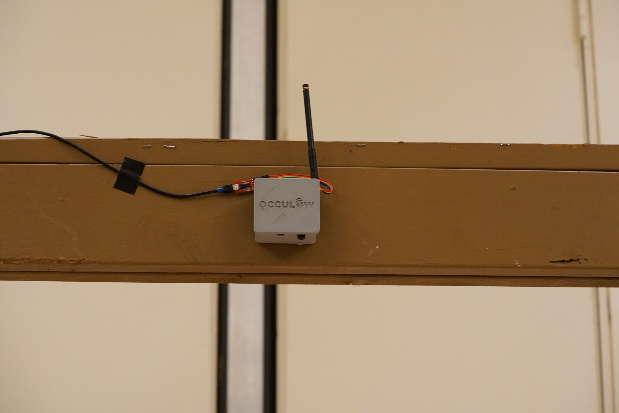
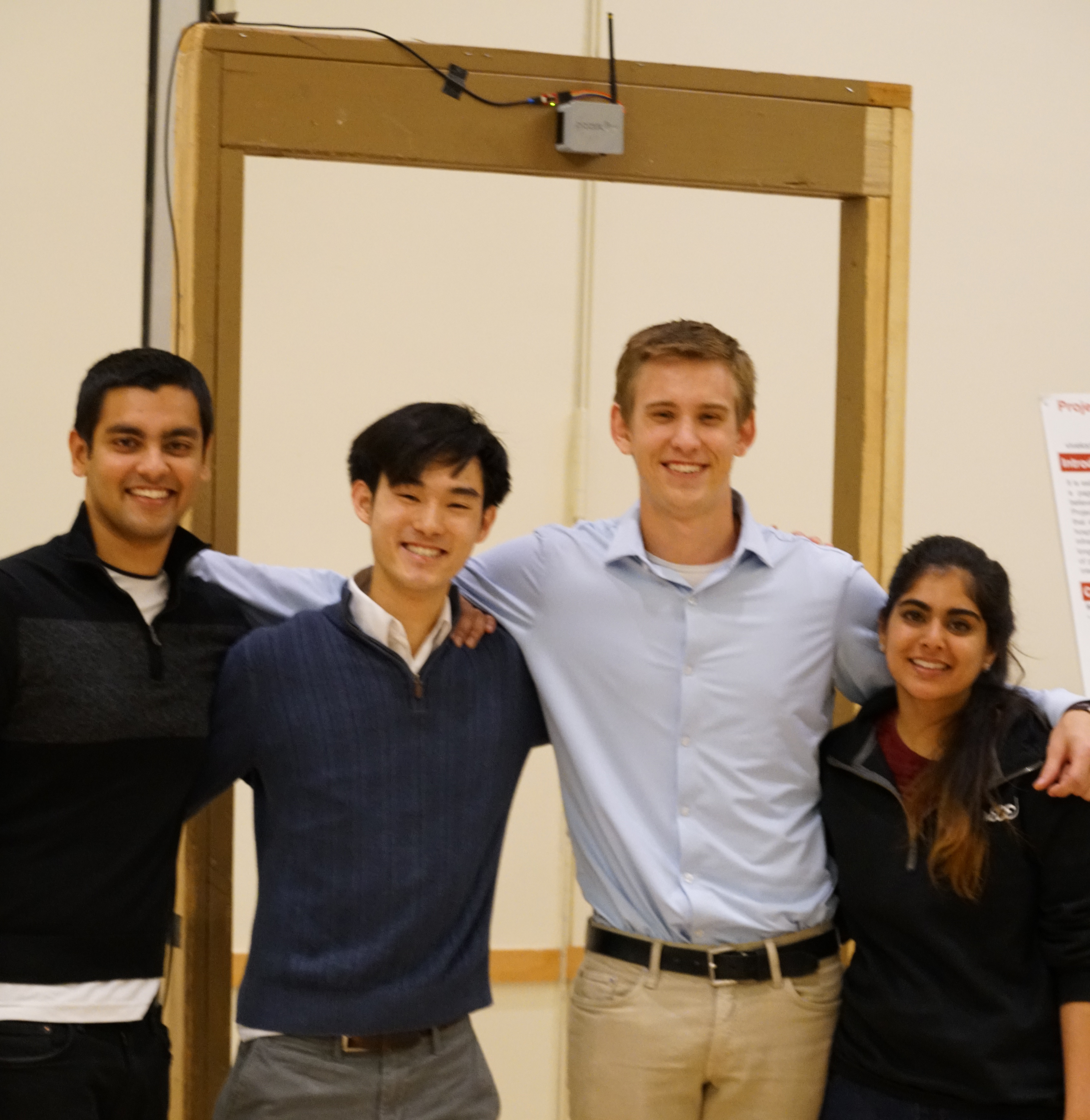
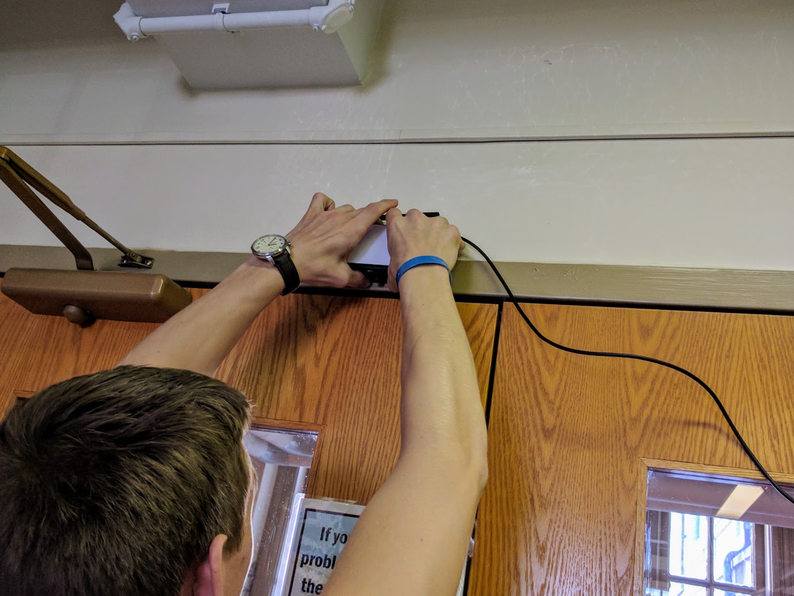
On May 12 we presented the final demo of our product to the public and a panel of judges from industry (Bosch, Intel) and university faculty. Shown in the image is our final integrated design mounted on a test doorframe. This prototype ran on 3 AA batteries (the wire was only used to capture heat map images for the demo), ideally for 8 months to 1.5 years.
At the end of the demo session, Occulow was selected by the judges as the best project! We are very proud of what we accomplished, but couldn't have done it without the help of the course staff. Thanks especially to Professor Rowe, Artur, and Craig for all of their support and advice.