Architecture

PCB

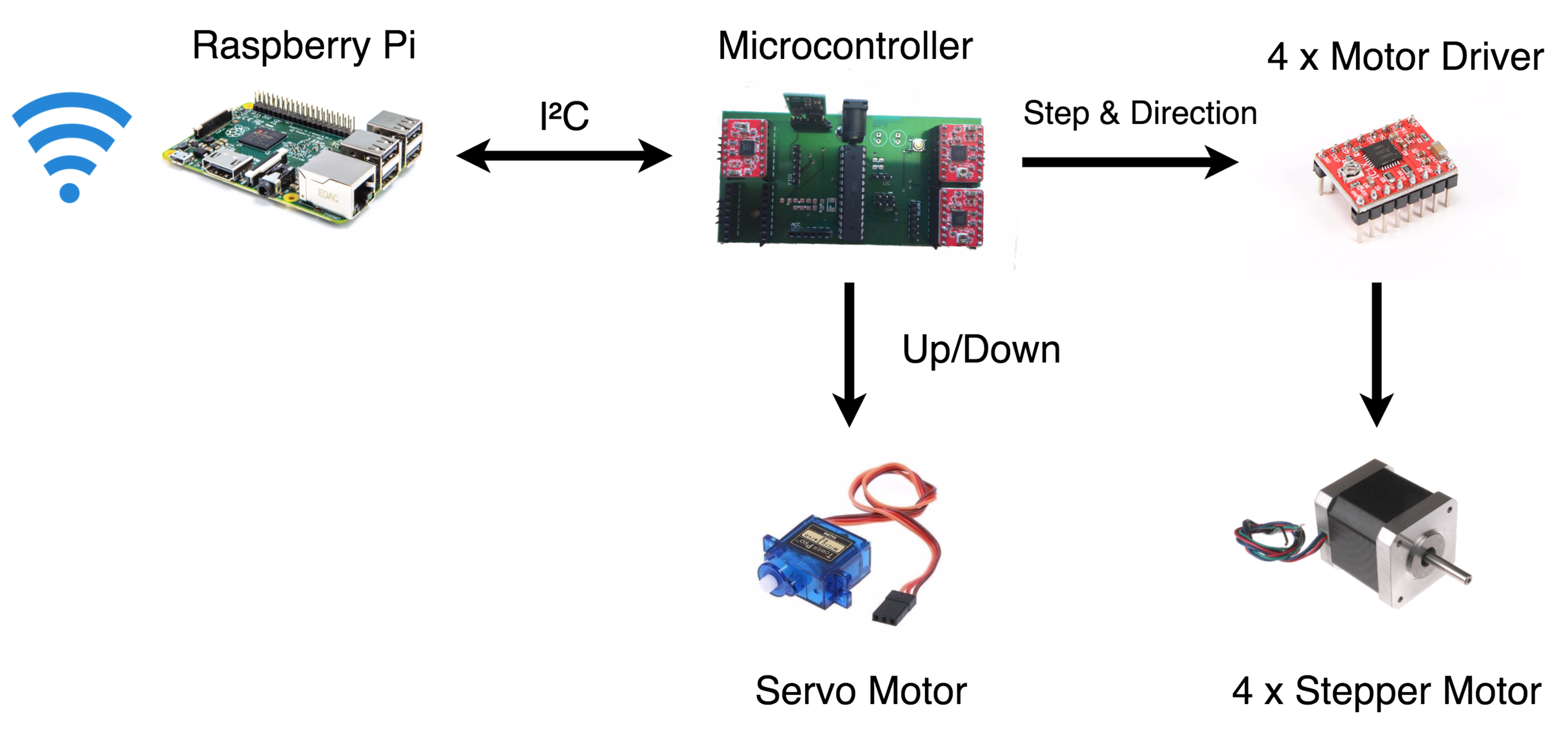
We designed our PCB to sit in the middle chasis that will be doing the drawing. Mounted on the PCB will be the 4 stepper motor controllers and those will be connected to the stepper motors via wires. The PCB will use I2C Protocol to communicate with the Raspberry pi. The PCB will be sent a number of commands for the stepper motors from the Pi and it will then send those commands to the stepper motor drivers.

Stepper Motor Mounts

The Stepper motor drivers will be connected to the Stepper motors via wire. The Stepper Motors will be mounted at the corners of the surface. We have 3D printed the mounts and allow the stepper motors to easily swivile around and change the direction they are facing if needed.

Raspberry Pi 2

The Raspberry pi will do the parsing of images into a list of points and then convert those points into commands for the stepper motors. The Raspberry pi will send the commands to the PCB using the I2C protocol. It will also be mounted on the chassis and the pcb will be mounted on top of the raspberry pi.

Demo of Parsing script result

The video shows the result of the parsing script applied to an SVG file. In addition another script is run to convert curves into a list of points. Once all the points are gathered it is then drawn. This is just a demo using Turtle in Python.

Architecture Diagram

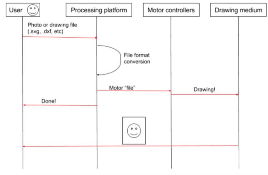
Use Case and Interaction Diagram

Figure 1

As detailed in Figure 1, a user interacts with the system by sending a file to a processing platform. The platform will then convert the file to a format understood by the motor controllers to draw. The motor controllers will command the motors to draw on the drawing medium (paper, whiteboard, chalk, etc.). When the motors are done drawing, the processing platform will notify the user it’s done and the user can now get their drawing, a perfectly drawn smiley face.

Use Case

The Use case is very simple. A user imputs an SVG image and the system draws it out.