TEAM 11: Chiron
Spring 2009
MEMBERS
- Rachata Ausavarungnirun
- Carl Vanderlip
- Wenyan Lu
- Kaimin Hu
PROJECT CONCEPT
We want to develop the "Basketball Training Glove" in order to adjust or train the
shooter's performance. This project will embedded sensors to the glove to measure
the shooting angle and shooting force; then, transmit the data for the analysis.
MOTIVATION
The current automatic coaching system is costly. The system that we
build will try to reduce the cost for basketball training.
COMPETITIVE ANALYSIS
NOAH basketball
coach training system:
- Using a fix camera to track the ball.
- Can only give response to the trajectory of the ball along with the "too short" or
"too long" response.
- The training video can be recorded.
- The cost is around $6,000.
TECHNICAL SPECIFICATIONS
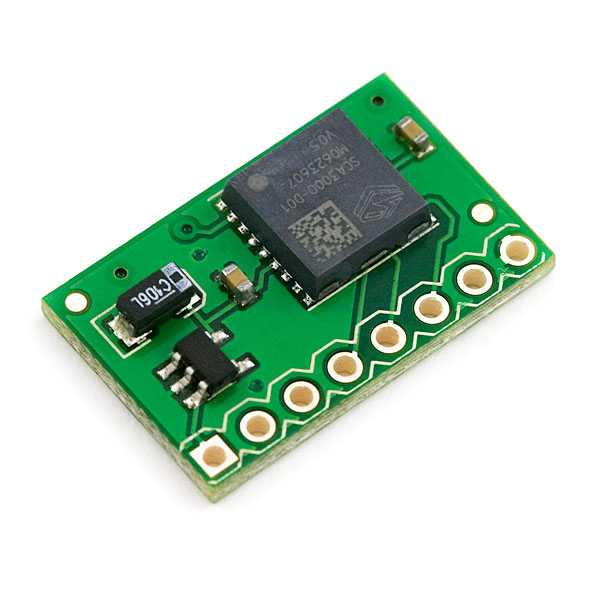
The glove embedded with sensors and accelerometer to
detect the shooter's angle and force when shooting, and send those data to computer
via bluetooth.
Hardware:
- 3-axis accelerometer, serial interface.

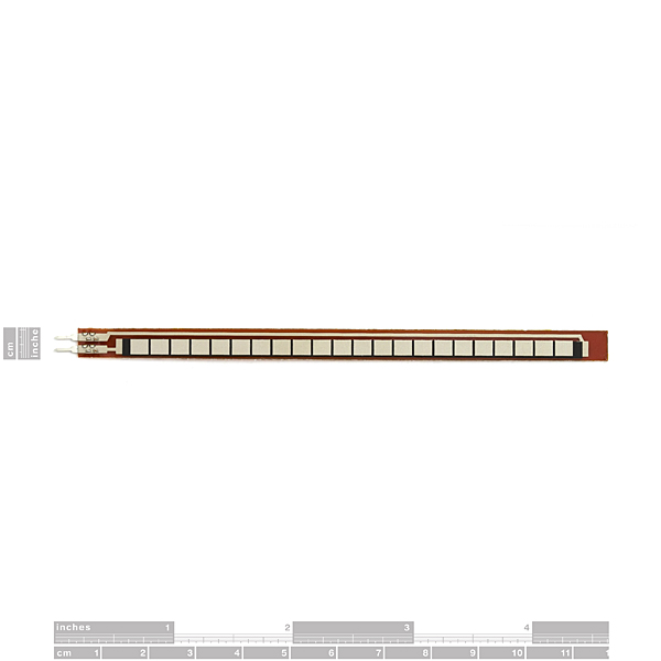
- Flex sensors.

- Gumstix with bluetooth. 400MHz arm with 64MB RAM, 16MB of flash and microSD adapter.
- Buttons for the reset state of the input.

- LEDs for the feedback.
- Glove.
- Basketball
Software:
- The software that compute the optimal angle, position, orientation and
acceleration of the hand. Then, give feedback via the LED.
Protocols:
REQUIREMENTS
- Functional Requirements: Accepting shooter's hand movement via the accelerometer.
Accepting the position of your arm with the flex sensors. Computing the accelaration
and orientation data with the gumstix and send those data to computer via Bluetooth.
The reset button is used once every session of the free throw.
- Timing Requirement: The system should give the result in a minute.
- Reliability: The hardware should be able to handle the contact with the basketball.
The system should not fail with the impact from the basketball.
- Portability: The system should be able to operate on the normal basketball court.
- Safety: The system should not hurt the player in any means.
ARCHITECTURE

USE CASES (INTERACTION DIAGRAMS)
A pdf file containing use cases can be downloaded here
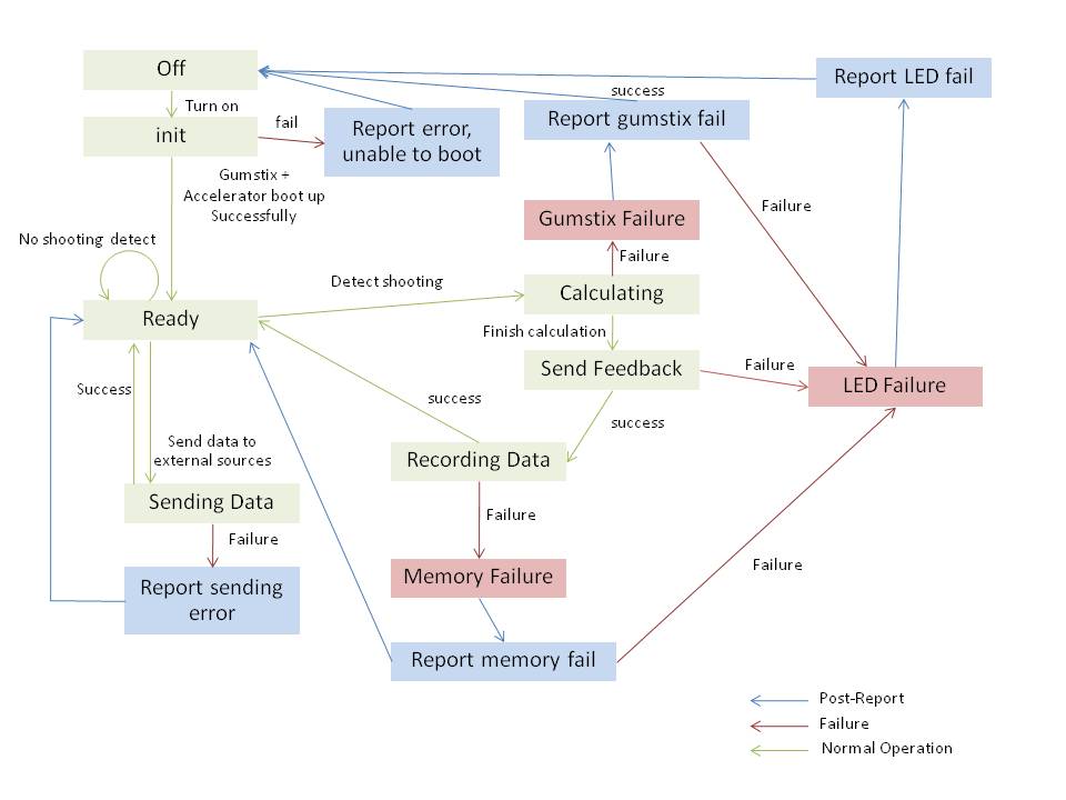
User start up the system: gumstix and accelerator board boot up. Once both are up,
it will send the data to LEDs prompting for user input via button.
User is pushing a "position" button: gumstix determine user current position based on the
corresponding button. Gumstix records any acceleration. Gumstix is on an active state.
User release the contact from the ball (detected via buttons) during the active state:
Gumstix calculate whether it is a dribbling or a shot. If it is a dribbing, stays in the active state.
If it is a shot, gumstix calculate the angle/acceleration/position of elbow and hands. Then give the feedback.
User in pushing a "send" button: gumstix transfer all the data to outside sources via bluetooth.
User power the system off: gumstix and accelerator halted.
Exception in the system: halted the system or report to user if we have memory exception.
SYSTEM STATES & TRANSITIONS

RISKS & MITIGATION STRATEGIES
Fundamental Risks:
- Hardware Interfacing - Get more familiar with SPI protocol between accelerometer and gumstix.
- Accuracy - Measure the performance of accelerometer after the parts arrive.
Ancillary Risks:
- Dead Reckoning - Calculate relative position based on accelerometer data and fixed initial position.If not feasible, have user input height with potentiometer.
- Timing constraints - Write efficient code to minimize feedback delay to user defined acceptable level.
ERROR HANDLING
Hardware Failure:
- power outage - restart the system once the power is back on.
- LED failure - When the user start the system, all the LEDs will flash. The user must detect the LEDs failure and find the replacement.
- Accelerometer.
- No incoming signal - Try waiting for several clock cycle, if the problem still persist, the system will force reset.
- Connection Failure - Report "need maintainance" on the corresponding LED.
- Buttons & flex sensor.
- Connection Failure or no incoming signal - Report "need maintainance" on the corresponding LED. (We can detect this case by interpreting data from the accelerometer)
Software Failure:
- Robostix Driver failure - force reset.
- Data get corrupted during the write to the port - .
- The SPI connecttion is lost - drop the problematic reading.
IMPLEMENTATION DETAILS
Robostix side:
- Robostix driver - Using the AVR library to set up an I2C communication between the gumstix and robostix.
- Connection - All the I/O excepts for SPI is connected via GPIO
Gumstix side:
- The C software that run the analysis and also filter the accelerometer input.
- SPI driver - sending data to the accelerometer via Robostix.
- The C software that control GPIO and receive the analog input from the flex sensors.
- All of these software will share some Global variable for the connection between programs.
TEST CASES
location tracker - This test will test the accuracy of the program and accelerator. It will find the location of the player given the initial position and set of input from the accelerometer.
This test will test how accurate the system is.
Normal shot tracker - Test the normal functionality of the system and check that it gives the feedback that make sense.
Power up/down - This will test whether it can handle power outage and reset it to the initial state or not.
I/O connection failure - This will test how the system handle the I/O communication failure, including how it output the failure through the LED.
Stress test for the software part - This test will test the functionality of the software, including how it handles shared variable.
EXPERIMENTAL EVALUATION
To be completed.
LESSONS LEARNED
To be completed.
FUN STUFF
To be completed.
REFERENCES
- Project Proposal and Requirements,
Team Project Presentation, February 1, 2008
- Design & Architecture,
Team Project Presentation, February 15, 2008
- Mid-semester Project Status,
Team Project Presentation, Date TBD
- Test Plan & Experimental Validation
Team Project Presentation, March 28, 2008
- Final Project Presentation,
Team Project Presentation, Date TBD
- Project Poster (pdf) (ppt),
May 2, 2008
- Project Video (m4v) (avi),
May 2, 2008
Back to the top of this page
18-549 course home page


