This week I worked on making the final presentation slides with Amelia. I also worked on integrating the PCB as part of the whole system with the Verilog team. I also fixed some of the soldering work on a LED that wasn’t working too well – the “i” on the lampboard – by desoldering it and moving to another pin on the shift register.. Finally, I continued working on the final report.
Weekly Status Reports
Nancy’s Status Report for 4/26
In the beginning of this week, I prepared for the final presentation and presented on Monday. Throughout the week, Amelia and I met to work on finalizing our integration between the RTL and the PCB. We were running into issues with our rotor settings (using the buttons and rotary encoder on the PCB). This took a lot of trial and error since it was hard to pinpoint what exactly was going wrong (the PCB itself, the individual modules, or their integration). We had made sure to test everything individually beforehand, so finally we realized the issue was the buttons on the PCB, since our implementation worked fine when we used the buttons on the DE-10 instead. We realized this was because we did not have any pull up or pull down resistors on the PCB. However, Amelia was able to work around this by having the buttons depressed while rotating the rotary encoder.
This upcoming week, we will finalize our poster, video, and report. I will also make sure we can demonstrate the RTL working on its own on the other DE-10 for demo purposes.
Team Status Report for 4/26
This week we started and finished the final presentation slides and Nancy gave an amazing presentation on Monday!
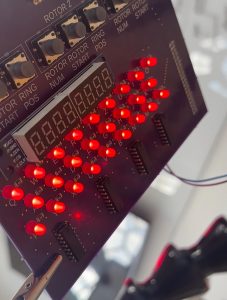
Tanisha also fixed the issue with the “i” on the lampboard by desoldering it and moving to another pin on the shift register.
Nancy and Amelia worked to fix the issues with the MAX 7-Segment glitching when trying to adjust the rotor settings. We realized this issue was due to lack of resistors on the buttons which left the input pin floating — giving us unpredictable and random signals, which caused the glitches. Nancy and Amelia fixed this by updating our RTL to change the rotor settings while the button was pressed rather than using a press and release FSM for the buttons.
In the next week, we need to finish the poster, make our video, and update our report.
Tests Run:
- Design rule check, verified design meets manufacturing requirements with 0 errors (PCB design)
- Electrical rule check, verified power and ground connections with 0 errors (PCB design)
- Continuity test on multimeter, ensure proper fabrication with 0 open circuits throughout board(PCB fab)
- Verified voltage levels at every connection for all LEDs, resistors and GPIO (rotary encoder, FPGA header, shift registers) (PCB fab)
- Validated 100% of traces by powering PCB and validating output voltage levels against schematic (e.g. LED on, logical high) (PCB fab)
- Peripheral unit tests: lamboard, light up random sequence of 50 letters (100% success)
- Peripheral unit tests: keyboard, continuously type for 2 min and ensure keyboard functionality (100% success) and lampboard functionality (100% success)
- Integrated user tests: test fully integrated product on 5 people, test and check encryption with online simulator (100% success on all 5 people for all encryptions)
Updates to Design:
- Moving from button press and release FSM to only changing settings on button press itself
- Remove microSD card functionality due to power constraints
Amelia’s Status Report for 4/26
Last Sunday, Tanisha and I started and finished the slides for the final presentation.
This week Nancy and I continued to work on trying to figure out the issue with the glitches when integrating the rotary encoder and the MAX 7-Segment display. We rewrote the code and FMSs multiple times when trying to figure out this issue. We had believed that the issue was with the MAX itself. However, one test we did isolated the PCB buttons and compared them to the functionality of the DE10 buttons. We realized that the PCB buttons were the issue and not the MAX. We realized that we had forgotten to add resistors to the buttons to prevent the input from floating which was exactly the behavior we were observing. Nancy and I realized that the only way the buttons could be functional was if they were continuously pressed because that is the only way to ensure the buttons are asserted low (buttons active low) and not at a weird floating value. To fix this, I changed the RTL so that you have to press the button for whatever setting you want to change while you rotate the rotary encoder. This ensures that we know what setting is being changed. Once I implemented this all the glitches on the MAX were gone. The glitches definitely were caused by the buttons being in a weird state. On Friday, I added a feature that blanked the MAX display when one setting was being changed in order to make it more readable. I also cleaned up some of the code. The RTL is pretty much complete now and we have implemented everything we had hoped to, excluding the button FSM which we fixed by holding down on the button when changing the rotors. I also started working on the poster due on Monday.
In the next week, we need to finish the poster, make our video, and update our report.

Team Status Report for 4/19
This week, we have made good progress towards integrating the PCB with the FPGA. Tanisha finished soldering the PCB and fixed one LED that was not lighting up by bypassing the trace and manually connecting an external wire/resistor to another output of the last shift register, which had unused outputs. She has verified the rest of the traces for continuity, setting us up for success when combining with the FPGA. One small issue is with the orientation of the rotary encoder, which we will need to finalize for aesthetic/functional purposes.
On the RTL side, Amelia and Nancy still have to work through some bugs with how the rotor settings are displayed on the external 7 segment display rather than on the DE10’s. We also hooked up the pins involving the display and the rotary encoder to the PCB and it was working the same! This was a good sign since we were concerned about if the FPGA’s 3V3 pin would be sufficient to power the PCB, but since the 7 segment display worked while all LEDs were illuminated, we should be good. We also got the lampboard to light up corresponding to our input from the PS/2, but still have some work to do with getting the output to display instead.
Finally, Amelia also worked on the housing for our FPGA & PCB. This was our solution to the loose header pins on the FPGA preventing us from getting a reliable connection. Since we are now using jumper wires between the two headers, we needed the PCB to be elevated above the FPGA, which also added some needed stability! Today, Amelia successfully laser cut the pieces and we will glue them together this week.


Tanisha’s Status Report for 4/19
This week I finished soldering our PCB and conducted PCB testing. I also started working on integration with the Verilog team.
I conducted extensive PCB testing throughout the week. I checked continuity for every connection on the board, checked each pin was supplying the appropriate power level, and power level at every connection and ensured it matches the schematic.
I also powered the PCB to ensure things were functioning and found all but one LED was working. I fixed this by trying to resolder the PCB, however in doing so I accidentally ruined a pad of the LED. However, I didn’t realise this at first so I worked on figuring out if the issue was with a dead LED, dead shift register, or a power issue.
By checking continuity and power outrages throughout the traces along the path of the power -> LED -> resistor -> ground, I was able to isolate the issue to be a lack of connection around the LED, hence realizing the pads were ruined. I solved this by incrementally soldering bare wire between the connections I wanted (power -> LED and LED -> resistor) till all connections were verified by both tests and finally the LED started working! The benefit of all of this means I am confident in the rest of my connections due to all of the debugging I did.
This is an example of skills I have learned over this past semester – trial and error by practicing my soldering and circuitry skills. I also learned more skills by asking other capstone groups for advice if they had encountered similar situations, I would say that was one of the most beneficial learning experiences I had. I also had practice outside of Capstone with TAing 18-349 where I had plenty of practice on laying out / fabricating and soldering PCBs.
The only task I have left for the PCB is fixing the rotary encoder as I laid the order of the pins out backwards on the schematic accidentally. I looked into a perf board solution to remedy this, but ultimately decided on adding another right angled header to try and change the direction of the encoder. I will also work on our final presentation and documentation for our final few submissions.
Amelia’s Status Report for 4/19
This was a very productive week! On Monday, Nancy and I fixed the bug we were facing last week with the rotary encoder not wrapping around from Z to A. We also added the RTL for the enigma rotor starting, rotor number, and ring position to display on the MAX seven segment display. We then implemented the rotary encoder modules with the rest of our integrated RTL. We are currently facing a few issues/glitches with the integration between how values are displayed on the MAX seven segment when the rotary encoder is turned.
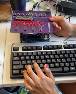
On Wednesday, Tanisha had finished running tests on the completed PCB and Nancy and I worked on integrating the current code and started working on the lampboard shift register logic. On Friday, Nancy and I started working on the shift register logic — we started with a single shift register with 8 LEDs hooked up on a breadboard. By Friday afternoon, we finished expanding this to the full PCB lampboard, here is a video of the lamboard integrated with the FPGA + PS2 keyboard.
Also, on Wednesday, I also created a CAD model of the wood housing for the PCB and FPGA and laser cut it on Saturday. Below is a picture of the wood housing with the FPGA inside and the PCB mounted on top!
I have learned so much over the course of this semester. One of the first challenges was hooking up the FPGA with all of the peripherals which required learning how to decipher several protocols (PS2, SPI). To do this I looked through old git repos and read lots of documentation and datasheets. The RTL we wrote for this project was much different than in any of the other hardware classes I’ve taken so far because of all the integration we had to do. This RTL also had to be synthesized on real hardware (which I haven’t done since 240) which had its own share of issues and required lots of heavy debugging and time spent on Reddit forums. I also learned how to CAD and use the laser cut software (CoralDraw) this semester for laser cutting the housing. I watched videos online to figure out how to CAD using onShape. I also asked some of my mechanical engineering friends for tips on how to make box joints. For laser cutting in TechSpark, I asked TechSpark employees for help and other students for help using the machine.
Nancy’s Status Report for 4/19
This week, Amelia & I worked on integrating our RTL with our many I/O components. On Monday, we fixed our issue with the rotary encoder skipping over values when going A-Z on our 7 segment display and then moved on to getting the rotary encoder to control the actual rotor settings, not just proxy 1-8 and A-Z variables. This led to some strange glitches that we then worked on debugging, which we still need to finish. On Wednesday, we worked on connecting the DE10’s GPIO pins to the PCB itself. This led to some strange issues, like some of the GPIO pins on the FPGA itself not working as expected, even when we just tested it with breadboard components. However, since Tanisha had gotten the PCB components soldered, we wanted to start working on the shift registers for the lampboard to make sure that worked as well. So, on Friday Amelia & I worked on getting the lampboard to work. We first started with a single shift register on a breadboard, and after some debugging, we got the lampboard to successfully display letters we input from the PS/2! This week, we will finalize our presentation and work on fully integrating, including working through the bugs with the 7 segment display and getting the lampboard to display the encoded data, not the PS/2 input data.
Over the course of this semester, I have learned a lot from this project. When selecting the right components, FPGA, and overall implementation, I had to read a lot of datasheets and documentation. While we’ve been introduced to this in classes before, it was definitely more daunting since there was less guidance, but overall it has made me more confident in my ability to evaluate the important information from these documents. Additionally, I had never worked with external I/O with an FPGA. This involved going beyond what I learned in 240/341. Similarly, we had to implement communication protocols at a lower level than using something like an Arduino library. This involved a lot of scrolling through the Internet on various forums and FPGA hobbyist blogs, as well as comparing Arduino library code to existing RTL implementations.
Team’s Status Report for 4/12
Two weeks ago we had our Interim Demo and received good feedback from this. We presented a working encryption scheme with inputs on the PS/2 keyboard and output displayed to the FPGA’s 7 segment display and using the FPGA switches as rotor dupes, a printout of our PCB with components laid out (since PCB was still being manufactured), and a presentation with our updated use case, design, and schedule. We felt that this Demo went well and based on feedback plan to update our final Demo to have 2 separate models – one with only the FPGA and one with both the FPGA and PCB to show off all the work we have done till now.
This past two weeks Amelia and Nancy worked hard on the rotary encoder RTL, wrote the entire SPI protocol for the MAX7219 7 segment display and integrated the encryption modules to work with all of the GPIO RTL they have written over the past few weeks and got everything working successfully!!
This week the PCB arrived (yay! see attached picture!) so Tanisha fabricated it and soldered all the SMD and PTH components on excluding the rotary encoder. Once that header arrives on Monday, she can solder it and the PCB fabrication will be complete. This week she will work on testing the PCB, completing her final report tasks and starting preparation for the final presentation.
For validation we will test our integrated system against results from each of our modular subsystems continuing on from our individual verification tests.
Meanwhile, the Verilog team will work on integrating the rotary encoder with the rest of the RTL and writing the RTL for the lampboard shift registers.
After the RTL is complete, the whole team will work on integrating the PCB with the RTL, carrying out user testing and planning the final demo set up. This all fits in to our planned schedule!
Nancy’s Status Report for 4/12
The past two weeks, Amelia and I have made good progress on the RTL. We currently have a working implementation of the rotary encoder, which can change the number displayed on the on-board 7 segment displays, but we do have some strange jumping issues when we try to implement it by scrolling through the alphabet, since there is some unexpected behavior on reset. Additionally, we spent the majority of our time working on the external seven segment display that uses the MAX7219 chip. We had a lot of trial and error trying to adapt Arduino library code and existing RTL code (that was in VHDL, not Verilog) to work in Verilog. We used an Arduino to verify that the display itself worked, but after a lot of debugging, we successfully displayed a message early this week!
Later this week, Amelia and I worked on expanding our implementation of the variable rotor settings. For our demo, we only had users change the rotor starting setting (A-Z), but still hardcoded the rotor type (1-5) and ring starting setting (A-Z). On Friday, we spent most of the day implementing this and got all of the settings to display on the external 7 segment display! These settings could all be changed using the switches and buttons on the DE-10 and we verified that changing these settings reflected in accurate encryptions using an online Enigma simulator.
Now that the PCB has arrived, Amelia and I need to start wrapping up our RTL. This week, we will work on the shift registers for the lampboard, which should be pretty simple, and we will debug the rotary encoder implementation too. This will keep us on schedule.
As Amelia and I have been working on the RTL, it was very helpful to verify the individual components along the way. This made integrating them much easier. For example, we first got the rotor settings to display on the on-board DE-10. Using the on-board I/O (buttons and switches), we verified that the rotor settings could be changed and that they were correct when compared to the original Enigma machine using an online simulator. This included focusing on edge cases like the wrap-arounds from Z-A and the transitions at the knockpoints, which cause the other rotors to rotate as well. We also individually tested that the 7 segment display worked, and then incorporated that with displaying the actual settings. We will continue to run these targeted tests around edge cases and plan on conducting user testing to see how people who are not familiar with the design will interact with it. We want to ensure that the encryption is always 100% correct.