Sebastian’s Status Report for 4/27

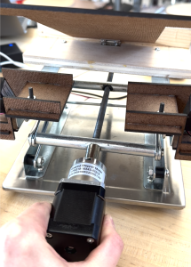
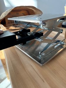
This week I researched and sourced new components for the stand. I measured the original lead screw dimensions of the stand so I could order a copy without a knob for use in the stand. I also sourced the right motor coupler to use so we can attach our motor directly to the new lead screw. This made much a much simpler and more effective design as shown in the image below.

I also started testing the new 5:1 motor with a gearbox and thankfully it has enough torque (as calculated) to fully lift the computer up and down the full range of motion. I did a series of up/down tests with the laptop on the computer stand to ensure that the motor had enough torque and endurance to meet the user’s demands in a worst case scenario. I did 3 up/down repeated tests. I also had to design and 3D print a custom motor coupler to perform the tests because the metal motor coupler had not arrived. As a result of the tests, we have concluded that the motor torque is sufficient.

Mary Rose’s Status Report for 4/27

This week I worked on preparing to give the final presentation and increasing the precision of the communication between the computer and the Arduino. I did this by changing my packet-sending system between the Arduino and the python code. It is not fully tested yet, but it should reduce our code’s reliance on delays. I also remade the motor housing to fit the new screw and motor with the gearbox, so the stand’s design will be fully completed by tomorrow when the 3-D print finishes.

I am currently on schedule. This week I plan on refining the serial communication for the rest of our tests and the final demo, working on the poster and final writeup, and possibly implementing Bluetooth communication

Mary Rose’s Status Report for 4/20

This week I worked on redesigning the stand, as well as re working some of the motor code.

First, for the stand, I designed the lip, the flap and the linear actuator shelves. Through some weight testing on the shelves, I determined that two seperate pieces would be much lighter, which would lessen the load on the height motor.  The first shelving unit I designed was not strong enough to hold the weight of the laptop, so I created another version that was stable enough. It will be connected to the stand via a 5/8 thick block that will be screwed into the top, with the two sides of the shelf screwed into it. I laser cut this, and made it extremely lightweight. For the lip, I decided that making this out of two wooden blocks (instead of laser cutting) was the only way to make it strong enough to support the weight of the laptop. I used pine wood because it is fairly light. And did some quick tests with the laptop to ensure that it is able to support it. I laser cut the flap as one T-shaped piece. I took some measurements to determine what the dimensions of the flap should be in order to keep contact with the linear actuators, and the lip. On the finished stand, the flap will be connected to the lip via a hinge. With these new components created, I was able to remove the metal top of the stand, which further lessened the load on the height motor.

For the motor code, I integrated the new code for the big easy driver, with the existing code for the linear actuators. I also wrote a simple turn-off function that will revert the stand to its base height and angle. I started implementing the rest of the FSM as well, meaning that the Arduino will no longer need to be reset each time the app is restarted. However, this code requires further testing.

I also did some research about gearboxes for the Nema 17, so that we would not need to switch to a Nema 23 motor, which would have required us to get a new driver and power source, which would have meant completely reworking the code.

While working on the project, I needed to create new components out of wood in order to preserve our budget and keep the top of the stand light. This meant learning how to use SolidWorks to create dxf files, and learning how to use the laser cutters in TechSpark. I was able to learn how to do this by watching videos online, and reading some articles about designing shelves. I also learned more about writing code for the Arduino, including using new libraries (AF_motor.h,   ArduinoBLE.h, AFMotor.h, and Stepper.h, and AccelStepper.h). I was able to find tutorials online about how to do this. Furthermore, I learned how to implement Bluetooth communication between a mac and an Arduino. To do this I found some articles online, and also watched some videos. 

Next week, I plan to have the stand design completely finished, meaning that all the top components are connected, and are the correct measurements. In addition, I plan to have the code for the motor and the linear actuators fully integrated and tested so that the stand moves as intended when given the correct serial commands.

I am a little behind schedule, but I should be able to have the hardware complete by the final demo. If needed, I will not implement the Bluetooth communication between the Arduino and the computer, as this is not necessary to achieve MVP.

The new components for the stand:

Sebastian’s Status Report for 4/20

Over the past two weeks my work has been centered on the mechanical structure of the computer stand and testing of the stepper motor. I designed and built a structure on top of the platform jack that allows the linear actuators to change the pitch of the computer. This involved machining, and screw hole placement.

I also performed testing on the stepper motor, testing the motor at a variety of different input voltages and speeds to determine if it has sufficient torque to lift the computer (it did not).

Before this motor testing, I also researched a constant current (chopper) driver for the motor because we realized that we were using the incorrect type of motor driver. After finding a suitable driver with the right input voltage range and pin connections to our arduino, testing was possible.

Since the motor still did not have enough torque after testing, I researched gearboxes that would make the NEMA 17 have enough torque. We found a gearbox with a 5:1 ratio and a torque of 3 Nm. I calculated that we require a torque of 4.4 Nm to lift the computer but this is the worst case when the stand is in a state that is rarely exercised (all the way down).

One of the new skills I learned was to calculate the torque required to rotate a power screw (a type of screw in a platform jack). This involved straightforward physics and allowed me to better judge what kind of motor gearbox we needed. I learned this skill from a video. I also learned how to measure the main characteristics of a threaded rod so I could easily replace it with another from McMaster. I used the McMaster guidance to learnt this.

Team Status Report for 4/20

Our most significant risk is generating enough torque to lift the stand. We are currently managing this risk by purchasing a new motor that has almost 7 times the amount of torque than the one we have now. Furthermore, we have developed some ways of lightening the top of the stand. If this does not work, we will buy a motor with higher torque by the end of next week. We can also start the stand at a higher position that the motor is able to lift.

We did not make any significant changes to the design of the system other than purchasing a new motor. We also decided to include a shelf to hold the linear actuators, although this change will not incur major costs or threaten our existing schedule. This was necessary so that the laptop will start at a lower angle.


Mary Rose’s Status Report for 4/6

This week I finished the serial communication between the laptop and the Arduino. While there are still some minor syncing issues with the current implementation, it is reliable enough to achieve MVP. In addition, I rewrote the code for the height and angle motors so that it will be compatible with the new motor driver. This includes a function that will allow the two linear actuators to move at the same time.

As of right now, I am a little behind schedule. Because of issues with the motor driver not providing the stepper motor with enough power, I was not able to get the hardware completely integrated, which would have allowed me to move on to integrating the Bluetooth setup. This week, I plan on finishing the hardware integration (with serial communication) and creating the top for the stand (with slots for the linear actuators) in Solidworks.

Team Status Report for 4/6

The most significant risks to the project are: the new motor shield not supplying enough voltage to the motor. From here we can go in two directions: we can order a higher torque motor, or we can use a shield with a higher input voltage. If our motor is not torque-y enough, we will pursue both options because we have money to spend and we need a short execution latency because we only have 3 weeks left.

The main change to the block diagram was using a new motor shield with higher input voltage. If that shield is not enough, we will use a driver with an even higher input voltage, however, since this driver is not a shield that means will need two arduinos, one to control the actuators and the other to control the motor. This will be more difficult to integrate.

We are on schedule.

Week specific answers:

Tests we have run: stepping the motor with the driver, stepping the motor while it is mounted to the platform jack, running the motor continuously while mounted (these tests tested the structural integrity of the motor mount and the torque of the motor), and also height/angle adjustment without using actuation (i.e. we use our hands to manually change the height and the angle of the computer).

Future tests to run: torque of motor with new motor driver, running motor continuously with new motor driver, structural test of linear actuator mount. When system is fully integrated: time to complete height/angle adjustment (our goal is < 5 sec). Total weight of system (our goal is < 8 lbs). When running height adjustment, we will see if the top platform tilts, the is not good because it means the computer might fall over. We will ensure that the stand does not change height too quickly so people do not hurt themselves when sticking their fingers in between the jack arms.

Sebastian’s Status Report for 4/6

This week, I completed the mechanical assembly of the motor mount. After Mary-Rose designed the parts, I 3D printed them, multiple times due to printer failure, and drilled holes into the main mount piece so screws could secure the mount piece to the screw of the platform jack. This also involved sanding the head of the screw so the motor mount could rest on a flat surface.

I also conducted basic tests on the motor to ensure that we can drive it and that it can cause the platform jack to elevate. The motor driver we used had a limit of 10 V, but our motor needs 12-24V. So when I increased the voltage input to the driver to 24 V, a capacitor on the driver exploded. After realizing we made a purchasing error, I researched other motor drivers and settled on the Adafruit Motor Driver v2, this driver has only a max voltage input of 12 V so we will see if it is capable of meeting our goals.

I also worked on the high level algorithm for stand adjustment with Olivia. Essentially, the stand will alternately adjust heigh and angle. The condition to stop height adjustment is when your face leaves the screen. The condition to stop angle adjustment is when your face is centered.

We are on schedule and this week we hope to complete the design for the linear actuator mount, mount the actuators, 3D print the linear actuator mount, drive the main motor at a high voltage with the new driver, and integrate the whole system.

Mary Rose’s Progress Report for 3/30

This week I created the parts that will hold the motor stable while it raises the laptop stand. This required precise measurements of our current design. The final pictures of these pieces are shown below. I also re-worked the motor code for both the height motor and the linear actuators so that it will work with the new library. In addition, I got started on implementing serial communication between the laptop and the stand as this is part of our MVP for the interim demo. Using serial communication will make it easier to communicate between the software and the stand for the demo, but we will rework this using the Bluetooth code i wrote earlier for the final product. I plan on having the serial communication finished and tested by next week, as well as the code for the stepper motor and the linear actuator fully tested, and I am back on schedule.

Sebastian’s Status Report for 3/30

This week I printed the motor mount pieces needed to attach the stepper motor to the platform jack. One of the motor attachment pieces is shown below.

The 3D printing was difficult because due to the size of the prints, the print failed twice. Currently, the last set of pieces are being printed and should be ready for test tomorrow morning.

I also researched how to drive the motors using the appropriate library, power supply voltage, and ports on the motor driver. We ran into a problem where we needed to use an older motor driver library that was incompatible with our Uno R4 so we had to degrade to an Uno R3 which worked well. We achieved motor spin.

We are behind progress because this week I was supposed to work on the posture detection neural net. Instead, I will work on that next week. I delayed this progress because this is not essential for MVP. Next week my main deliverable will be training the neural net.