Team Status Report for 4/27

Tests

Response Time: 

We found that we had a response time of 50ms. This estimate is what we found to be a ceiling estimate of the longest response from the carrier to track. Based on the results we believe that we should be able to position the stops between the carrier and coil to be able to account for the delay and properly propel the coil in a sightly manner.  We anticipate that the Arduino response time will be somewhat variable and should be fast enough for our needs despite the added delay that comes from the serial Bluetooth communication. No design changes are needed based on the results of this test. 


Risks

Speed-Up Coil

When it comes to the coils, it seems like the height of the coil is to big for the carrier to pass over, which was not anticipated until recently as previous tests showed that just the carrier itself could go over the coil, but now with the circuitry added and weight being an issue now, this is a risk since if the coil isn’t short enough, then we run into the issue where the carrier would just stop at the speed-up coil, and not be accelerated by the coil, which are detrimental to the project. The point of the coil is to allow the carrier to be propelled across the track and if the height is an issue such as now, then we can not propel the carrier across the track. With this being an issue, we arrear now looking into altering the design of the spool for the coil as well as considering other changes like reducing components on the carrier as well as removing the battery form the carrier in order to reduce the weight of the carrier which would then increase the levitation from the track for the carrier, which would then allow the carrier to pass over the coil easily.


Design Changes

Decided to go with a smaller height for the speed-up coil spool in order to allow the carrier to pass over the coil when traveling on the track, since weight is now a huge factor to this project.


Schedule

No change in our schedule.

Test

Response Time: 

We found that we had a response time of 50ms. This estimate is what we found to be a ceiling estimate of the longest response from the carrier to track. Based on the results we believe that we should be able to position the stops between the carrier and coil to be able to account for the delay and properly propel the coil in a sightly manner.  We anticipate that the Arduino response time will be somewhat variable and should be fast enough for our needs despite the added delay that comes from the serial Bluetooth communication. No design changes are needed based on the results of this test. 

Speed Up Coils

When it comes to testing the speed-up coil, we tested which coil produces the most magnetic field based on the radius, the type of AWG Copper Wire, the amount of current going through the coil, turns, etc.

With these results, we can easily tell that the coil with 22 AWG with a radius of 0.75 inches, 230 turns and 5.1 Amps which produces .012 Tesla, that this coil is the one that produces the most magnetic field. When it comes to the final product, we know that this coil produces a powerful magnetic field, but we need to consider the smoothness of the carrier when it passes over the coil. With that being said, we tested where on the coil the back end of the carrier should be positioned to maximize smoothness and distance traveled from the propulsion. We marked the spool with a sharpie and confirmed visually that the carrier can smoothly travel about one section of the track in length without nose diving and maintaining stability.

Levitation and Stability

The remainder of our test was completed through visual inspection. We looked at how well our carrier levitated and propelled on the track to determine whether they meet our standards. For levitation, we wanted our carrier to continuously levitate regardless of its location on the track. With our final design—2cm magnets with no spacing for the carrier and 2.5 cm rectangle magnets no spacing for the track—we were able to achieve this. For stability, we wanted our carrier to continuously and evenly propel, regardless of location on the track. This was also achieved with this current prototype. Past prototypes magnet shapes caused parts of the track to be attracted to edges of the magnets, causing irregular propulsion. The new design has eliminated this issue.

Angel’s Status Report for 4/27

  • Team Meeting (4 hrs)
    • Worked on final prototype
  • Mandatory Meeting (4hrs)
    • Watch Final Presentation
    • Provide Final presentation feedback
  • Independent Work (4 hrs)
    • Work on final presentation
    • Create final carrier prototype.
    • Work on creating remaining parts of the track

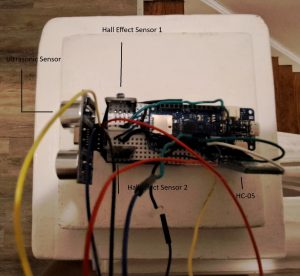
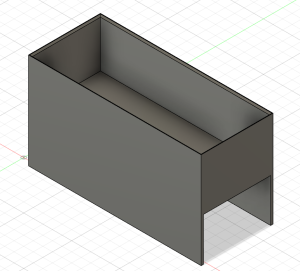
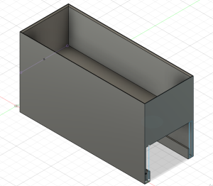
This week, I worked on creating the final version of the carrier. We decided on making the final version of our carrier 7 cm (sanded down to reduce to friction) to fit on a 6.5 cm track. The carrier has linear hall effects on both sides of the track to detect stops on either side of the track. We also placed the breadboard on a particular part of the carrier to ensure that the weight was balanced. This meant the carrier would properly propel when stimulated by the coil and levitate evenly.

We also worked on making progress on our track. Due to issues with 3D printers, we were not able to print the remainder of our track. Because of this, we were limited in how we were able to test our track. We attempted to test our propulsion  on 1/3 of the track (the current prototype we have). We did so by attaching our coils to H-Bridges, setting up the code to progressively propel the track, and seeing how successful the propulsion was. This propulsion was successful for the carrier if there was no battery attached. While we can power the carrier circuit through a long wire opposed to a battery, this would look messy and force us to continuously mindful of the wire as the carrier propels. We have created alternative spools that will create shorter speed coils. We hope that with this design, the carrier w/ a battery can propel successful. We plan to test these new spools with our new, longer track.


Next Week

We will print the rest our track and finish integration of our system.


Angel’s Status Report for 4/20

  • Team Meeting (3hrs)
    • Worked on final presentation
    • Discussed how we will combine the different components of the project
  • Mandatory Meeting (4hr)
    • Make design changes for the track
    • Work on final paper
    • Work on final presentation
  • Independent Work (8hr)
    • Work on final presentation
    • Work on paper
    • Make design changes for the track


This week, I worked on editing design changes to the track and carrier. The previous carrier had 1cm of space between magnets. We removed the space between the magnets to increase the magnetic field and make the carrier more stable. Also, the height of the carrier was increase to leave more room for levitation and the speed up coils. This design was printed along side our track with rectangular magnets. These were tested and we saw significantly more stability with this version. Also, since we are not using circle magnets for the track, the carrier does not get stuck in gaps along the track, something that previously made stability and levitation difficult.

I also worked on updating the final paper and final presentation. I used the feedback we received from the design review to edit sections that need more detail for the final paper. I worked with my teammates to complete the different sections of the presentation.

Next Week

Next week, I will work on the final paper, final poster, and prepare for the live demo.

Additional Guidance

In order to complete this project, I needed to relearn how to use CAD . I have used CAD  in a  Mini Course to complete a final project but have not used the software since. We needed to create 3D printed models that meet particular design requirements to meet our minimal viable product. This meant I had to spend a significant amount of time relearning the basics of CAD and learning how to implement the features we specifically needed.

To relearn CAD, I focused on looking over documentation, working through designs inclemently, and reaching out to an expert when I was confused.  For this project, I decided to use Fusion360 for my CAD designs. Given that Fusion is used widely in engineering, I was able to find documentation online. It went over the basics of the software and showed how to inclemently combine features to make particular designs. This information allowed me to start testing my knowledge of the software through making parts of the track and carrier design. Working inclemently through particular designs like the rail or the magnet spacing allowed me to better understand features in CAD and how they can be used collectively. However, given I am still a beginner in the language, I often ran into problems. Luckily, I have a friend in the Mechanical Engineering that helped explain difficult features and debugged  my CAD errors.

Angel’s Status Report for 4/6

  • Mandatory Meeting (4hr)
    • Interim Demo
    • Adjust CAD Design to match design requirement
  • Independent Work (8hr)
    • Adjust CAD Design to match design requirement
    • Work with two linear hall effect sensors

This week, I worked on updating the CAD designs we have to match our design requirements. There were several issues with the 3D printed version of our design. One major problem was there were very small gaps between the track and the carrier. This limited the mobility of the carrier, which would affect the carriers ability to levitate and propel. I adjusted the gaps between along the rail of the track to be wider. Also, with the current design, the carrier could levitate at most 1 cm. Given that our cardboard prototypes levitated 1 inch (2.54 cm), this gap is not large enough. Also, speed up coils will be placed directly above the track, something that could increase the height the carrier levitates. This gap was adjusted to 3.5 cm to allow the carrier room to levitate as much as needed.

I also worked on the stops for the track. In order for the carrier to detect a stop, a magnet has to be within 1.5 cm of the magnetometers. I created stops along the track that are 4 cm above the track to account for carrier levitating, the speed up coils, the thickness of the 3D printed carrier and breadboard, and the height of the linear hall effect sensor with the magnetometer. The stops are also design to be 1cm away from the carrier.

I also worked on adding solidifying the ranges for the magnetic field of different stops. The magnetic field values that determined if the carrier were near a stop all worked within 1.5 cm but all had different gaps between the cut of value and the value within 1.5 cm. For example, the right magnetometer values were too high for the negatively polarized magnet, meaning the magnet could be significantly further than 1.5 cm to get a good reading. While this isn’t a problem, it would be good to be consistent with the gap between the cutoff and the expected value. I adjusted these values so this gap was around 50 units for each possible stop.

Next Week

I would like to print updates to our prototypes to see if they match expectation.


Angel’s Status Report for 3/30

  • Mandatory Meeting (4hr)
    • Discuss design changes for the track
    • Go over feedback from design review
  • Independent Work (8hr)
    • 3D print two-to-one track with rail and smaller carrer
    • Work with two linear hall effect sensors to solidify
    • Work with ultrasonic sensor
    • Updated block diagram


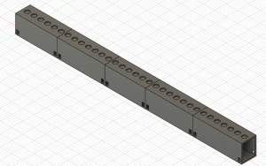
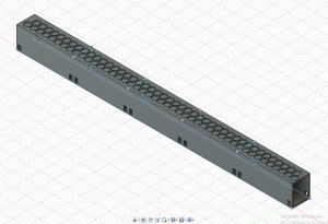
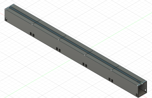
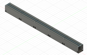
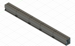
This week, I worked on printing initial versions of our final track. Since the two-to-one track/carrier magnet prototype was more stable, this is the design that was printed. The printed track is 1/5 of our final design, making it 20 cm long. The width is 6.5 cm to be able to hold speed up coils with an approx. diameter of 6 cm. The height is 7 cm to have enough room to support the track and levitate the carrier an inch (2.54 cm). The size of the carrier was reduced to reduce cost and to give easy access to the circuit that will be placed above the carrier.

I also worked on testing the two magnetometers as stops for the track. To do this, I connected three LEDs to the Arduino that would light up depending on what was in front of the magnetometers. The yellow LED would light up if there was no magnets in front of either magnetometer. The red LED lights up if there is a negatively charged magnet next to either magnetometer. The green LED lights up there is a positively charged magnet next to either magnetometer. This will be used to help debug stops along the track, something that will be controlled through wireless communication between the track and carrier Arduino. We expect this step to be complex so this circuit will helpful through the process

I also worked on the ultrasonic sensor. The ultrasonic sensor is suppose to stop the carrier if something is within 10 cm of the track. This requires wireless communication, something we have not solidified. To test this at the moment, I am using a red LED that lights up if something is within 10 cm of the carrier breadboard.

I also begin working on the HC-05 wireless communication. Given that we are still working on our speed up coils, I am testing this with a separate Arduino uno and the Arduino MKZero on the carrier. I am in the process of debugging the code for the “receiver”, or the arduino uno. For the wireless communication, the carrier, (if it sees a stop or an obstruction) sends information to the track (to slow down/speed up the track depending on the case). For the HC-05, this done through writing and reading different serial outputs. Each arduino has different ways of reading/writing to a serial. I am in the process of debugging the serial for the Arduino Uno. The serial I used in the MKZero is not accessible for the Arduino Uno.

Breadboard for the carrier

Next Week

I plan to further debug wireless communication so we can test how the track arduino and carrier arduino will communicate. Also, I want to work on design how the magnets will be placed along the track to make a stop,

Team Status Report for 3/23

Risks

One major risk for our project is the speed-up coils. While working on the solenoids, we realized that we didn’t produce enough magnetic field to propel our carrier. We confirmed with testing with a singular magnet that the magnetic field we have produced is strong enough to propel the magnet, but the goal of these coils is to propel the carrier across the track. We have made changes to our solenoid such as changing the radius, changing the amount of turn, and  the location of the solenoids on the track. We calculated that we produced a stronger magnetic field but have also run into the same issue of not being able to propel the carrier. This poses some risk for our project since the MVP heavily relies on being able to move the carrier along the meter long track.


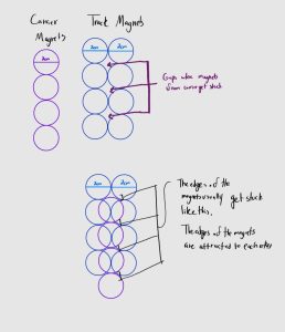
Another risk for our project is the stability of our carrier. The stability of our carrier is determined by the ratio and of magnets along the track and carrier and the design of the track and carrier. We started working on the two-to-one track design due to issues with stability in the one-to-one option. While this was slightly more stable, we noticed that magnets would get stuck in gaps in between groups of magnets. The stability of the carrier on the track affects the ability for the whole maglev train to be successful.


Design Changes:

We have decided to make multiple changes to our solenoids such as increasing the radius of the turns, the location of the solenoid on the track, etc. in order to help produce a stronger magnetic field to propel the carrier. We found out that using the casing of the 24 AWG Copper Wire allows for a larger radius for the turns as well as more stable and tighter turns, thus helping out in producing a larger magnetic field.


We have ordered rectangular magnets. They will be an alternative to the two-to-one circle magnet track with less possibility of magnets getting stuck do to their being no major gaps between the magnets (they create a straight line).

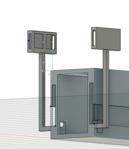
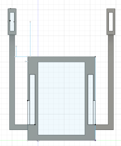
We have a CAD design with a guide way for the track. This would limit the movement of the track, decreasing the chances that the track would flip over.


Schedule Change:

We are on schedule


Angel’s Status Report for 3/23

  • Ethics Meeting (2hr)
    • Discusses Ethics of our project with class
  • Independent Work (10hr)
    • Construct cardboard model of two-to-one carrier/track magnets design
    • CAD design for one-to-one carrier/track circle magnets design
    • CAD design for two-to-one carrier/track circle magnets design
    • CAD design for two-to-one carrier/track rectangle magnets design
    • Determined a way to distinguish stops with a magnetometer


Through out this week, I worked on solidifying the dimensions for the one-to-one track/carrier magnet design and the two-to-one track/carrier magnet design. The main changes to models involved spacing out the magnets on the carrier for the two to one magnet. This mainly do to not having enough magnets when I constructed the cardboard prototype but this design was significantly more stable than the one-to-one design but also levitated higher. However, there were still some issues with the magnets getting stuck in between gaps in the track. This was a large reason why we decided to order rectangular magnets


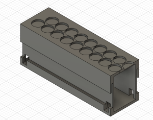
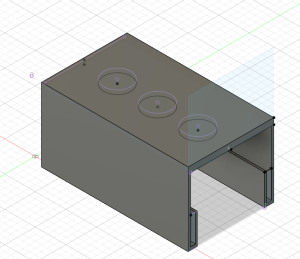
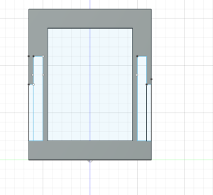
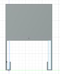
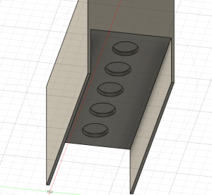
I also constructed CAD models for the different designs. For track designs, I created  the  one-to-one track circle magnet design, the two-to-one track/carrier circle magnet design, and the track design for the two-to-one track/carrier rectangle magnets system(pictures below). The circle magnet designs are based of the finalized dimensions from the cardboard prototypes. Since the rectangle magnets have not come in yet, this design was based off of predicted behavior based on what we have seen with the circle magnets and the dimensions of the rectangle magnets. One major consideration for the rectangular design is how to orient the magnets. Currently, the longer side of the rectangle is along the track and  there is large gap between the lines of magnets. While the magnets are less likely to get stuck since it is a straightaway, sudden movement in the carrier could result in sides of the magnets getting stuck like in past designs. I would like to create a cardboard prototype of this structure then edit the current CAD design based on the results.

One-to-one track/carrier circle magnets

Two-to-one track/carrier circle magnets

Two-to-one track/carrier rectangle magnet (2mm between lines)

Two-to-one track/carrier rectangle magnet (10mm between lines)

Carrier

Bottom of Carrier

I also created  a derivative of the one-to-one design with a guiding rail for the carrier. This would be in place to help with the stability. This was difficult to construct with cardboard so I would like to print this soon to see if the dimensions of the rail properly account for the height of levitation and sudden movements with the carrier.

One-to-one guided design

Side of one-to-one guided design

Carrier guided design

Side of carrier guided design

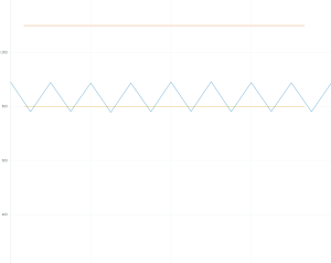
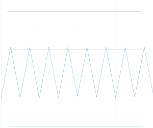
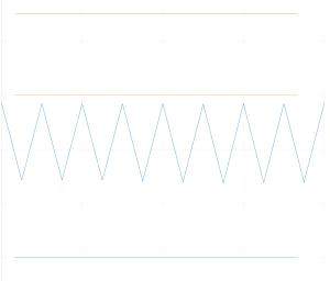
I also worked with magnetometers to attempt to make a stop start system. This was done  though attaching two magnetometers to face opposite sides of a breadboard to simulate the sides of the carrier. I tested how the plot changed as I moved magnets along both sides and switched their polarity while adjusting the sensitivity of the magnetometers. Following a few tests, I noticed that the amplitude of the signal on the plot changed based on the polarity of the magnets, the amount of magnets, and the magnetometer the magnets was in front of.  Based of this, I think a baseline signal can be created and significant changes in either side of the signal can represent a stop.

No Magnet near either magnetometer

Negative polarity near magnetometer 1


Negativity polarity near magnetometer 2

Next Week

Next week, I would like to work on making more carrier designs.  Also, I would like to print some portion of all the above designs to see if there are any major design issues I missed. I would also like to continue working with the magnetometer and start working with the ultrasonic sensors to make a full start, stop system.

Angel’s Status Report for 3/16

  • Weekly Team Meeting (2hr)
    • Discuss design changes for the track and carrier t
    • Discuss how to best implement the ultrasonic sensor and linear hall effect sensor
  • Mandatory Meeting (4hr)
    • Discuss design changes for the track
    • Go over feedback from design review
  • Independent Work (6hr)
    • Change one-to-one carrier/track magnet design
    • Reattempt two-to-one carrier/track magnet design
    • Test linear hall effect sensor


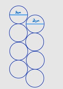
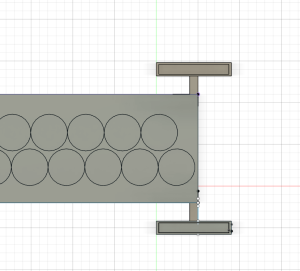
Through out this week I spent time working on the design of two prototypes. I rebuilt the straight away one-to-one track with less spacing between the magnets to stop magnets from the carrier getting stuck. While this helped with that problem, it made it clear that a one-to-one system is unstable. I attempted to redesign the two-to-one carrier/track. In this design two aligned rows of magnets were placed on the track. However, given that the magnets are circular, parts of the track had gaps as seen in the picture below. These gaps resulted in carrier magnets getting stuck on the track.  I have created a new design in which the magnets (2cm diameter) are misaligned by 1cm. I plan to implement this design early next week.

I also tested the linear hall effect. I tested how the linear hall effect behaved when a magnet was near the sensor, far from the sensor and when a magnet moves along it. I used this information to better understand the data I was receiving from the Arduino and how to interpret that information into something usable.


We updated our schedule earlier this week to more accurately reflect what we have complete and what we know hope to complete. Therefore, I am currently on schedule.


Next Week

In the following work, I plan to build my new design for the two-to-one track/magnet design. I also want to work with my teammates to see how to add a speed coil to the one-to-one track/magnet design given its only problem currently is stability. Lastly, I would like to start signal processing for the linear hall effect sensor.


Angel’s Status report for 3/9

The following work was completed between 2/25 – 3/9 (week prior to spring break – end of spring break)

  • Mandatory Labs (4hrs)
  • Individual work (6hrs)
    • Finalized straightaway cardboard prototype with cardboard carrier
    • Attempted to create straightaway cardboard prototype with cardboard carrier
    • Modify CAD design for straightaway track and carrier prototype
  • Design Report (6hrs)
    • Complete Design Trade Studies and System Implementation

Through out the past two week, I have spent time further developing cardboard prototypes for the track and carrier maglev. I attempted to create two prototypes for the straightaway track and carrier. The first involved having a 1-1 relationship between the track magnets and carrier magnet. While this design successfully levitated the carrier, there were issues with stability. In attempt to create a more stable design, I created a prototype with a 2-1 track magnet to carrier magnet ratio. Due to errors with spacing (the track magnets were too far apart on the track), this design created a carrier that was attracted to the space between the track magnets, resulting in no levitation. I plan to reattempt this design with less spacing between the track magnets to see if the system will be more stable.

Also, completing the initial straightway track and carrier from cardboard showed that the spacing in the current CAD design of the straightaway track is too large. The best spacing between ends of a magnet is roughly 3 centimeters. I plan to make modifications to all CAD track designs to meet these specifications.


Next Week 

In the following week, I hope to start printing the CAD design for straightaway track and carrier. Secondly, I would like to start working on a prototype for the oval shaped track. Lastly, I would like to start working with the ultrasonic sensor and the hall effect to start to design the start, stop, and speed system.

Angel’s Status Report for 2/24

This Week 

  • Weekly Team Meeting (6hr)
    • Created cardboard prototype of carrier and track to test levitation and strength of magnets
    • Adjusted CAD design metrics to better fit result from cardboard prototype
  • Mandatory Meeting (4hr)
    • Watched design review presentations and provided feedback
  • Independent Work (2hr)
    • Created cardboard prototype of carrier and track to test levitation and strength of magnets
    • Researched different designs of model maglevs to get ideas on how to improve the prototype

Through out this week, I spent time working with the new supplies we received. I developed a cardboard track and carrier with elongated sides (both with magnets) to test the strength of our magnets. The magnets were very strong, which often lead to the carrier flipping over. After the carriers elongated sides were adjusted and the carriers length was extended, levitation of the carrier stabilized at around 1 inch. I plan to adjust the CAD design of our carrier and track to better match these results.

We are currently behind schedule but we plan to adjust our schedule to match our progress

Next Week

In the following week, I hope to print the CAD design of the track and carrier and test its levitation. If all goes well, I plan to work with my teammates to attached the speedup coils and test the propulsion.