Jason’s Status Report for 12/7/2024

WORK ACCOMPLISHED:

This week I focused on conducting tests of the physical capabilities of the skateboard to ensure it is able to survive whatever turmoil our users may put the board through. This includes traversing different terrains, applying different levels of force to the board while riding, and monitoring the overall wear and tear through expected usage such as the return to me.

Background: To provide some context, turning without a rider on board involved us spinning one wheel forward and the other backward to kind of skid the board into a new arrangement/ alignment. As a result, the board’s back wheels experience significant wear from this process to the point that we notice significant marking on the wheels after only a few weeks of testing. In the future, we would likely reimplement this project with harder grade wheels to ensure the wheels last longer.

Testing: I first tested with riders of varying weights and sizes from 110 pounds up to 220 pounds and a height of 5’3 up to 6’2. The board operated equally well on all and none of the tested riders reported anything under a 5 when asked to rate their comfort levels while riding. The board was able to move without any slow start or stalling and could maintain speed with every rider.

I next tested the terrain capabilities by riding over cement, grass, asphalt, and some areas of very high small pebble/ rock frequency. The skateboard performed very well on cement and asphalt, less well on grass, and the worst on the rocky area. The enclosure sustained some light scratches but otherwise stayed attached and showed no signs of bolts or nuts loosening.

I also did some work on the GPS soldering and beginning the setup of the advanced, more precise gps system.

Progress: We will be ready to demo all of our working features next week.

NEXT WEEK’S DELIVERABLES:

  • RTK GPS data integration and a more accurate/succesful return to me
Jason’s Status Report for 11/30

WORK ACCOMPLISHED:

The enclosure is complete and we have drilled escape holes for the battery charging port and the power button as well as passthrough holes for the motor wires and the front gps/LiDAR cables. The enclosure has been assembled and I added a ring of insulating material that will help waterproof the enclosure as well as reduce the gap between the enclosure and the board as a result of the deck’s innate curvature. Holes have been drilled into the skateboard to attach the enclosure to the board and corresponding hardware has been selected to attach. On top of this, I wrote code to execute a basic demo of object avoidance. In essence, the skateboard “sees” the object, backs up, turns to avoid the object, accelerates past the object, stops, turns back on course, and continues moving. A video of this demo is in the slack channel.


PROGRESS:

As we have likely given up on the LiDAR, we are essentially done with our project. We will be working to improve GPS accuracy with some parts that just came in to work closely with the radio tower in Hamerschlag. Other than that, we will be finalizing our slide deck to present in class

NEXT WEEK’S DELIVERABLES:

    • Completed project/ slides


Jason’s Status Report for 11/16/24

WORK ACCOMPLISHED:

A lot of progress has been made but at a cost of a step backward. So the LiDAR compatibility with the raspberry pi has been a thorn for the last week and a half and a few days ago, I threw in the towel and outsourced. The first group I met with was Robo-club as we were using their 3d printers anyway. They had me follow some guides but I have followed most of the available info online already. When this did not work, I scheduled a meeting with a PhD student in Professor Rowe’s lab. After about two hours of debugging, he came to the conclusion that this LiDAR model is simply not compatible with our RbPi OS. We confirmed this by trying with an older model, a d435. When this worked, he let me borrow a d435 and we proceeded from there, concluding it was not possible to connect a d455. In addition, we have 3d printed an enclosure for our parts to sit underneath the board.  We used a slightly modified version of a design found on thingiverse and will compile pieces tomorrow. I also wrote code to back up and move around an object that has been detected. Now, I need to write code with the new LiDAR to obtain a point cloud to be able to recognize objects and their size to move around them.

PROGRESS:

THe progress was monumental this week and we got over the LiDAR hump. We will grind tomorrow to produce a good demo and then in the subsequent week to piece all the parts together.

NEXT WEEK’S DELIVERABLES:

    • Completing an object detection/avoidance end to end pipeline and to smoothly integrate that with the return feature
    • Complete chasis by resizing enclosure, drilling LiDAR holes, drilling enclosure holes, drilling holes in enclosure for charging and power button
      • Hopefully obtain some shorter wires
      • bring velcro, window sill liner for enclosure


Jason’s Status Report for 11/9/2024

WORK ACCOMPLISHED:

This week, we experimented significantly with turning and began to connect more extraneous pieces together. In the turning department, we initially struggled with our old deck and acceleration step of 0.01 duty cycle. I read online that in order to turn properly, we should consider lowering our duty cycle to give the wheels a better chance to grip the ground which ended up helping significantly. We also shortened the wheelbase by swapping the deck out with a deck I had at home, which also improved our steering by a landslide. We are now able to make stable right and left turns. We have also decided to return to the user from the back (as in the back wheels when riding will lead when returning) as this makes it easier with steering. We have also made strides with GPS routing.

As we swapped LiDARs this week, I have spent the last 2ish days trying in vain to connect the LiDAR to the Pi. I have followed a few tutorials and will be asking for help if I cannot accomplish this task in the next day or so. The documentation is shaky at best as you have to make a very custom package build on the pi to allow pysense (intel real sense on a pi) to run properly.

PROGRESS:

We are still a little behind schedule. The blockage of the pi connection to the LIDAR has presented another unforeseen issue in our progress forward. While we have delivered on all of the things promised last week, I would like us to be able to detect objects in the next few days so we can figure out our path planning and start testing that aspect.

NEXT WEEK’S DELIVERABLES

We will have some path planning/ return features implemented. We will also be directly controlling/testing from the phone at that point.

Jasons’s Status Report for 11/2/24

WORK ACCOMPLISHED:

This week, we focused on getting motor movement from a python script. While we struggled with this initially, we managed to get a response once we switch from connecting from the GPIO pins on the Rpi to the COMM ports on the vesc to using the USB ports on both. Prior to this, we attempted sending signals via pyvesc, sending independent UART signals, and sending PWM signals. We are now able to control each motor independently and I have tinkered with acceleration and deceleration curves and have tuned to a point where we can begin testing. I will further refine once we have mounted. Currently, I have a test bench in which I control motors with keyboard interactions. The only thing left to solve in simultaneously control which I believe we will be able to do with multithreaded listening for commands for each motor.

PROGRESS:

We are a little behind schedule. The documentation for pyvesc is very skim and it appears projects like this are quite rare. As a result, it is taking longer than expected to navigate this package and figure out some intricacies.  Getting a response from the motors is a huge step forward and unlocks so much more for us now. We will likely be able to make very large bounds in the next few weeks.

NEXT WEEK’S DELIVERABLES

We will have app to motor response, rudimentary turning, and a jank assembly of the board complete.

Jason’s Status Report for 10/26/2024

WORK ACCOMPLISHED:

This week I focused on starting the assembly of our parts. I soldered bullet connectors onto our VESC to allow it to connect to the motors. I soldered the VESC to the anti-spark switch which connects to our power button and prevents surging when the battery is initially powered on. I soldered the anti-spark switch to an xt60 connector which allows us to connect to the battery. Ultimately, we were able to power on the VESC, making a huge progress step for us.

PROGRESS:

We are slightly behind on tasks but should be able to make significant progress this week. I have been slightly delayed by one part taking longer than expected to arrive but have been preparing in the meantime. The next steps are to test the python code I have written on the VESC. Currently, I am blocked by a part that connects the motors to the VESC and thus I am unable to presently test the Pi-VESC communication.

NEXT WEEK’S DELIVERABLES

The missing part is expected to arrive this weekend. When it does, I will begin testing and tuning the Pi code. Next week, I expect to be able to control motors from the webapp and begin setting acceleration curves in preparation for mounting on the board.

Jason’s Status Report for 10/19/24

WORK ACCOMPLISHED:

I dove back into VESC software and realized we may not be needing it but will likely instead be replicating the functionality. 

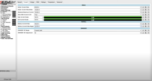
One crucial component when using VESC software is motor configuration. Above is a screenshot of the VESC software. When setting up the VESC with this software, we are setting important things such as Voltage Limits, Current Limits, Motor RPM Limits, Temperature Limits, Motor Tuning, Startup Boost, and Regenerative breaking. In the absence of a VESC, my plan to tackle each of these is as follows:

Voltage Limits/ Current Limits: We will calculate our battery and VESC’s voltage limit and place ceilings on the speed of the motors relative to the cap we impose to make it physically impossible to exceed our limits, even at maximum motor speed. In the case where this is not possible or does not prove to be effective, we will add external current-limiting circuits with a current/voltage sensor.

RPM: We will use Hall sensor data to keep a close watch on the RPM and throttle if we exceed a certain limit we will impose. This can be done through RPi packages.

Temperature: Similar to RPM, our hall sensors will allow us to understand the temps of our motors at any given time. We will have a circuit-breaker esque trip system that will cause the board to slowly come to a stop if we exceed same measurements.

Motor Tuning: We will likely have to measure the motors with an LCR to determine the resistance and inductance to help define how we will set our acceleration curves.

Startup Boost: When in the initial phase of the motor, we will supply slightly extra current to avoid dead-stop stalling.

Regenerative Breaking: We will not be incorporating this feature.


PROGRESS:

I am on track with my goals as set out by the Gantt chart. I am somewhat blocked in waiting for the VESC to arrive to begin applying the theory and ideation to a practical and testable environment to begin making adjustments as necessary. When we return to school, I will be able to work on this in a much more effective and efficient manner.


NEXT WEEK’S DELIVERABLES:

  1. Assemble as much of the board as possible.
  2. If the VESC is here, begin running tests and playing around
    1. Specifically decide concretely about UART vs PWM.
  3. Ensure we are able to read data from the Motors and send it back to the RbPi.

Jason’s Status Report for 10/5/24

WORK ACCOMPLISHED:

Part list changes: We elected to convert from our existing GPS IMU selection here: https://www.sparkfun.com/products/16329 to this one: https://www.sparkfun.com/products/22693.  The course staff chose to buy this and it outperforms our old pick significantly. The last option provided 2.5 meter accuracy and the new one is 0.01 meter accuracy, which allows us to meet our user requirements. The only consideration here is that the data output is slightly different so we will have to adjust our method of processing. This also frees up more budget to allow us to get closer to the $600 mark. We also swapped to a new LiDAR that the course staff provides. The new LiDAR does not connect directly to our Qwiic parts so we will be swapping to a USB-C to connect.  This also saves us significant budget.

We also solidified a number of connections and finished ordering parts. Once the parts arrive, we will be able to further solidify the designs. I plan on tinkering with all the parts in the lab to get a better understanding of how each one works and the data output we can expect from each one. The finalized parts list is here: https://docs.google.com/spreadsheets/d/1ouYsHj6s2zO1oddGNwvI4KCI4vJLrQ7ma_3bCsAnZ94/edit?gid=0#gid=0

The last major design change was a transition to a external battery pack to power the Raspberry Pi. We are concerned about splitting power from the huge pack so we are using an external pack. We could not find a 5v/5a external pack so we converted to a Raspberry Pi 4 instead of 5 to make it more accessible for common power packs. The only concern here is we will have to drill an additional hole in the enclosure to allow for charging. In addition, having 2 chargers is a little bit of an inconvenience.

I also did a preemptive diagram of all of our connections and the ports to ensure each one is compatible and able to transfer the data and power that we need.

PROGRESS:

I am on track on progress despite taking longer than expected to finalize the parts list. We went through a number of iterations including frequent group meetings, a meeting with Joshna, and frequent discussions with professors after class.


NEXT WEEK’S DELIVERABLES:
The next step for me is to receive the parts and start piecing things together to get closer to the final product. I will continue to help my team with app design, LiDAR sensing, and GPS mapping. The biggest task next is to figure out the autonomous steering mechanism and the communication method between the RbPi and the VESC. Before the parts arrive, I will familiarize myself with the open source VESC software to be prepared to jump in when all parts are here.

Jason’s Status Report for 9/28/24

WORK ACCOMPLISHED:

Further research into part compatibility has demonstrated the following problem. As we are already facing budget concerns, we are very mindful of any increases to our total costs. I discovered that the battery we selected does not come with a bms or battery management system, a critical component for obtaining live data with regard to battery charge. As this was one of the core requirements we set out for ourselves, we want to push to accomplish this goal.

Our current battery is 10s2p which means 10 in parallel, 2 in series for a total of 20 batteries at $90. Moving to a pack with a bms even at 6s2p, which is 12 batteries brings us up to $185 as seen here: https://www.mboards.co/collections/batteries/products/6s-p42a-battery-pack-transparent-series with very little opportunity for other options.
As a result, we remain undecided.

We consistently have to make tradeoffs between reputation and performance.   For instance, we are able to buy more powerful motors with hall sensors here https://www.amazon.com/Brushless-Belt-Drive-Balancing-Scooters-Skateboards/dp/B07RXWW3DS/ref=sr_1_12?crid=2NEHK9FI43FHT&dib=eyJ2IjoiMSJ9.6_nUl4ZD3ZhjtZRfEZjPpPkI-0W-ird_zf3qSUvrDoYUGkNTVwylh-QgjidNUhGbBe8Qa_XTIE045heaKbB5qKbSCZ6tp3QndVmnl9liKLtqRwtL1AC–_CNs96VuNbYgxfPJvtUo_kl6qI-aVew-xXCn2bupq9aYjwABIzz8FzucCxE36cwUdnpagXtLfcBK5erniMT3015ZyDPIe9Mm4gaoM9hpidCoyrb6UavlVlui1HrwVHDXP2RGIHHI577Q3uZjiODNIhXDbX7rnCcJO6g-03lSZ_WOywLBtRB8rw.E1N2p-XUPUVELYuiIRbatHIXFuBrgDPEFet7I_SFGso&dib_tag=se&keywords=skateboard%2Bmotor%2B6354&qid=1727576364&sprefix=skateboard%2Bmotor%2B6354%2Caps%2C116&sr=8-12&th=1
but without the ratings and brand reputation that our other option gives us.

On top of this, I researched the charger for our battery, antispark switch to power the board, and explored the wirings for our VESC and made note of some converters we will need to purchase.

I also looked into the truck/motor mounting system and found

which we will likely use as it appears to be relatively plug and play

DISCUSSIONS:

I researched the communication methods between the Rpbi and VESC and landed on using UART. Theoretically, we can use UART to send motor speed, temperature, and others to the Rbpi and receive throttle, braking, and other commands back. There is a python module called pyvesc that will allow us to do this seamlessly.

The VESC does not explicitly list compatibility with UART but says it is compatible with VESC software. In the case it is not compatible, we will definitely be able to send PWM signals to the motors from the VESC using RPi.GPIO python module and the GPIO ports on the Rbpi.

I also discussed path planning with Tio and the team and landed on a project of GPS down to a 2d box in which we will use basic x,y coordinates to reach the target.

PROGRESS:


I am still on track as my task this week was to select the path planning algorithm.


NEXT WEEK’S DELIVERABLES:

Next week, my sole goal is to fully and completely finalize the parts list. There is still considerable work to be done on this front and I hope we are able to get this done so we can move on to the actual implementation. This has proved to be significantly more difficult than expected.


Jason’s Status Report for 9/21/24

WORK ACCOMPLISHED:

Landed on a solidified architecture for controller to board communication.
The flow will be as follows.

In the event of normal riding, our flow will be input from user on webapp -> bluetooth communication to raspberry pi -> raspberry pi to VESC communication of signals -> VESC to motors

In the event of the “return to me” feature, our flow will be input from user on webapp -> bluetooth communication to rasberry pi -> input from LiDAR sensor to raspberry pi -> path planning calculation on the web app -> directions sent to raspberry pi -> directions sent to VESC -> directions sent to motors.


Part Selection:

  • Landed on an almost-final version of the parts we will be employing.
    • VESC: https://flipsky.net/products/dual-fsesc4-12-100a?variant=9022834638908&currency=USD&utm_medium=product_sync&utm_source=google&utm_content=sag_organic&utm_campaign=sag_organic&gad_source=1&gclid=CjwKCAjw0aS3BhA3EiwAKaD2Zd5iglwJYeZaNOX5BAR4TkeQuqevF_zDt3az7iHfjzF1aVxhLHioOhoC1rkQAvD_BwE
    • 2x 5055 motors: https://www.amazon.com/Hobbyhh-Brushless-5055-400KV-Efficiency-Aircraft/dp/B09BYVKZ5W/ref=sr_1_2?crid=F1IOMBUFCJGT&dib=eyJ2IjoiMSJ9.YIcSePfgaVsN6txie0egmwsARIbLiLZgkDep_XMtgkBZ48uyUE-Bgfs2PnUpL4Tzld0_cKCw4WfuliYydziJmzvCVVH7j8HK2DLiDKXKFYpvkwgklkCSKVAfWKhmS51yGr04LtxTChMIHHGz2P-7HteXbZ5jz4_VQE1rC8LA2kruijlqTRfQe7ytiWh-B36U59Fcbog-XeS5GYgmFXH0S-JPCSWt8fuD1-8DCrpFwQ4eO9xw7Iw0vmxQUxG7mOkWmbkssPNsyoN1JPxpTmU12v4wypoSK778X7mkfMDxETg.V86EyqCGVVZR9GmM6c0lQvJXmOMAs4k0VaUqd1ns8YU&dib_tag=se&keywords=5055+motor&qid=1726985746&s=toys-and-games&sprefix=5055+motor%2Ctoys-and-games%2C289&sr=1-2
    • The build above minimized spending but allows us to meet the requirements we specified in our abstract and in our proposal presentation

Discussions:

  • More info about architecture: The VESC turns out to be necessary due to power consumption concerns: the raspberry pi is unable to regulate and control the amount of voltage and current needed to power the motors. As a result, we cannot circumvent the VESC and must use a rbpi alongside a VESC.
  • On the topic of belt driven vs hub motors, I have elected to go with belt motors as we likely cannot sustain the cost of hub motors. Above is the candidate I have chosen. We are sacrificing ease of configuration for cost and potentially slightly more torque.
  • There are a variety of open source path planning algos but for our sake, I think ML may be unnecessary as we plan to essentially implement a simple “back up and reroute” algo. As a result, I have elected to largely ignore available path planning algos.

PROGRESS:

I am on track as I was supposed to explore path planning algos and assist with part planning and both of those items have been accomplished.


NEXT WEEK’S DELIVERABLES:

Next week, I aim to complete the following:

  • Have a more concrete and mathematical approach to the path planning algo including GPS movement from point A to point B, object sizing algorithm ideas, and ideating on how much to back up in the case of an obstacle occurrence.
  • I want to get my team approval on my parts selection and submit it to the TA for ordering
  • I will also help prepare design presentation slides and write speaker notes to help whoever presents
  • I will also continue to coordinate with professors and our TA as well as make relevant updates to the slack and website