This week, I was able to successfully finalize the audio localization mechanism.
Using matlab, I have been able to successfully pinpoint the source of an audio cue with an error margin of 5 degrees. This is also successful for our intended range of 0.9 meters, or 3 feet. This is tested using generated audio signals in simulation. The next step for the audio localization is to integrate it with the microphone inputs. I take in an audio input signal and pass it in through a bandpass to isolate the audio cue we are responding to. The microphone then keeps track of the audio signals, in each microphone for the past 1.5 seconds, and uses the estimation mechanism to pinpoint the audio source.
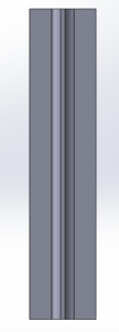
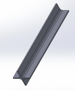
In addition to this, I have 3D printed the mount design that connects the servo motor to the head of the robot. This will allow for a seamless rotation of the robot head, based on the input detected.
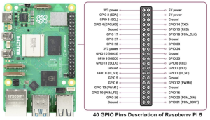
Another key accomplishment this week is the servo motor testing. I ran into some problems with our RPi’s compatibility with the recommended libraries. I have tested the servo on a few angles, and have been able to get some movement, but the calculations based on the PWM are slightly inaccurate.
The main steps for servo and audio neck accuracy verification is as follows.
Verification
The audio localization testing on simulation has been conducted by generating signals in matlab. The function was able to accurately identify the audio cue’s direction. The next testing will be conducted on the microphone inputs. This testing will go as follows:
- In a quiet setting, clap twice within a 3 feet radius from the center of the robot.
- Take in the clap audio and isolate ambient noise through the bandpass filter. Measure this on a waveform viewer to verify the accuracy of the bandpass filter.
- Once the clap audio is isolated, make sure correct signals are being passed into each microphone using a waveform viewer.
- Get the time it takes for this waveform to be correctly recorded, and save the signal to estimate direction.
- Use the estimate direction function to identify the angle of the input.
To test the servo motors, varying angle values in the range of 0 and 180 will be applied. Due to the recent constraint of neck motion of the robot, if the audio cue’s angle is in the range of 180 and 270, the robot will turn to 180. If the angle is in the range of 270 and 360, the robot will turn to 0.
- To verify the servo’s position accuracy, we will use an oscilloscope to verify the servo’s PWM, and ensure proportional change of position relative to time.
- This will also be verified using visual indicators, to ensure reasonable accuracy.
Once the servo position has been verified, the final step would be to connect the output of the estimate_direction to the servo’s input_angle function.
My goal for next week is to:
- Accurately calculate the servo position
- Perform testing on the microphones per the verification methods mentioned above
- Translate the matlab code to python for the audio localization
- Begin final SBB body integrating


