Mahlet’s Status Report for 12/07/2024

This week, mainly consisted of debugging my audio localization solution and making necessary changes to the hardware of SBB. 

Hardware

Based on the decision to change motors from servo to stepper, I had to change the mounting mechanism of the robot’s head to the body. I was able to reuse  most of the components from the previous version, and had to make the mounting stand slightly longer to be in line with our use case requirement. Now the robot can move its head very smoothly and consistently. 

My work on audio localization and its integration with the neck rotation mechanism has made significant progress, though some persistent challenges remain. Below is a detailed breakdown of my findings and ongoing efforts.

To evaluate the performance of the audio localization algorithm, I conducted simulations using a range of true source angles from 0° to 180°. The algorithm produced estimated angles that closely align with expectations, achieving a mean absolute error (MAE) of 2.00°. This MAE was calculated by comparing the true angles with the estimated angles and provides a clear measure of the algorithm’s accuracy. The result confirms that the algorithm performs well within the intended target of a ±5° margin of error.

To measure computational efficiency, I used Python’s time library to record the start and end times for the algorithm’s execution. Based on these measurements, the average computation time for a single audio cue is 0.0137 seconds. This speed demonstrates the algorithm’s capability to meet real-time processing requirements.

In integrating audio localization with the neck rotation mechanism, I observed both promising results and challenges that need to be addressed.

For audio cue detection, I tested the microphones to identify claps as valid signals. These signals were successfully detected when they exceeded an Arduino ADC threshold of 600. Upon detection, these cues are transmitted to the Raspberry Pi (RPi) for angle computation. However, the integration process revealed inconsistencies in serial communication between the RPi and the Arduino.

While the typical serial communication latency is 0.2 seconds or less, occasional delays ranging from 20 to 35 seconds have been observed. These delays disrupt the system’s responsiveness and make it challenging to collect reliable data. The root cause could be the Arduino’s continuous serial write operation, which conflicts with its role in receiving data from the RPi. The data received on the RPi seems to be handled okay, but I will proceed to validate the data side-by-side, and make sure the values are accurate.  Attempts to visualize the data on the computer side were too slow for the sampling rate of 44kHz, leaving gaps in real-time analysis.

To address hardware limitations, I have temporarily transitioned testing to a laptop due to USB port issues with the RPi. However, this workaround has not resolved the latency issue entirely.

Despite these challenges, the stepper motor has performed within expectations. The motor’s rotation from 0° to 180° was measured at 0.95 seconds, which meets the target of under 3 seconds, assuming typical latency.

Progress is slightly behind schedule, and the contingency plan for this is indicated in the google sheets of the team weekly report.

Next Steps

Resolving the serial communication latency is my highest priority. I will focus on optimizing the serial read and write operations on both the Arduino and RPi to prevent delays. Addressing the RPi’s USB port malfunction is another critical task, as it will enable me to move testing back to the intended hardware. Otherwise, I will resort to the contingency plan of using the webapp to compute the data. I will be finalizing all the tests I need for the report, and finalize integration with my team over the final week.

Mahlet’s Status Report for 11/30/2024

As we approach the final presentation of our project, my main focus has been preparing for the presentation, as I will be presenting the coming week. 

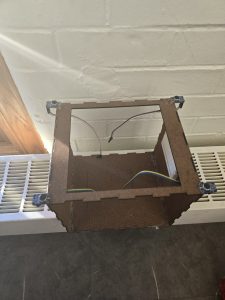
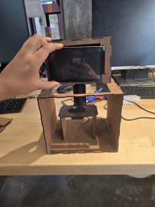
In addition to this, I have assembled the robot’s body, and made necessary modifications to the body to make sure every component is placed correctly. Below are a few pictures of the changes so far. 

I have modified the robot’s face so that it can encase the display screen. Previously, the head was a solid box. The servo to head mount is now properly assembled. The head is well balanced using the stand I used to mount the motor to. This way there is space to place the Arduino, speaker and RaspberryPi accordingly. I have also mounted the microphones to the corners as desired. 

Before picture: 

After picture: 

Mounted microphones on to the robot’s body
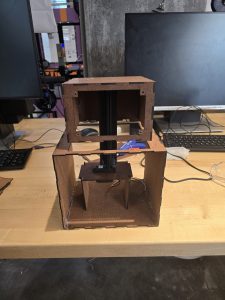
Assembled Body of the robot

Assembled body of the robot including the display screen
 

I have been able to detect a clap cue using the microphone, by identifying the threshold of a loud enough clap detectable by the microphone. I do this processing in the raspberry pi, and once the RPi detects the clap, it runs the signal through the direction estimate function, which spits out the angle. This angle is then sent to the Arduino to modify the motor to turn the robot’s head. Due to the late arrival of our motor parts, I haven’t been able to test the integration of the motor with the audio input.  This put me a little behind, but using the slack time we allocated, I plan to finalize this portion of the project within the coming week.

Another thing I worked on is implementing the software aspect of the RPS game, and once the keypad inputs are appropriately detected, I will meet with Jeffrey to integrate these two functionalities. 

I briefly worked with Shannon to make sure the audio output for the TTS through the speaker attached to the RPi works properly. 


Next week: 

  1. Finalize the integration and testing of audio detection + motor rotation
  2. Finalize the RPS game with keypad inputs by meeting with the team. 
  3. Finalize the overall integration of our system with the team. 

Some new things I learned during this capstone project is how to use serial communication between Arduino and a raspberry pi. I used some online Arduino resources that clearly teach how to do this. I also learned how to perform signal analysis on audio inputs to localize the source of a sound within a range. I learned how to use the concept of time difference of arrival to get my system working. I used some online resources about signal processing, and by discussed with my professors to clarify any misunderstandings I had towards my approach. I also learned from online resources, Shannon and Jeffrey how a WebSocket works. Even though my focus was not really on the web app to RPi communication, it was good learning how their systems work.

Team’s Status Report for 11/30/2024

For this week, one risk that we are taking on is adapting the DSI display touch screen to use the keypad for inputs instead. We want to complete the pipeline of keypad to RPi5 to Web App. The Web App and RPi5 connection is working well currently, using socket.IO to maintain low latency communication. However, the next step is having keypad inputs as opposed to using the DSI display touchscreen while maintaining the low latency requirements. While it is possible that we will have some difficulties with a smooth integration process, we do not foresee any huge errors/bugs occurring. Nevertheless, should we get stuck, the mitigation plan is to use the touch screen of the DSI display.

Another minor but potential risk during the demo is that given that our project assumes a quiet study environment, the audio detection relies on identifying a higher volume threshold for the double clap audio cue. If we are in a relatively noisy environment, there is a risk of interference in the audio detection mechanism. One way to mitigate this risk is to increase the audio threshold in a noisy environment, or performing the demo in an environment the project assumes. 

One major design change is regarding the audio input mechanism. Since the RaspberryPi does not have an analog to digital converter, we have used an Arduino to get the correct values for the audio input for audio localization. This did not affect the schedule, as it was easily integrated into the integration portion of the system. Budget wise, this did not incur any budget constraints as we used an Arduino we have from a previous course. Other than that, we haven’t made any changes to the existing system design, and are mainly focused on moving forward from risk mitigation steps to final project implementations, to ensure our use cases are addressed in each system.

The schedule remains the same, with no updates to the current one. 

Overall, our team has accomplished:

  1. WebApp implementation
  2. Audio Response feature (position estimation with 5 degrees margin of error) 
  3. Partial Study Session implementation (WebApp to RPi communication completed)
  4. Partial RPS game implementation
  5. TTS Feature (able to play audio on the robot’s speaker) 

More details on each feature can be found in the individual reports.

Mahlet’s Status Report for 11/16/2024

This week, I was able to successfully finalize the audio localization mechanism. 

Using matlab, I have been able to successfully pinpoint the source of an audio cue with an error margin of 5 degrees. This is also successful for our intended range of 0.9 meters,  or 3 feet. This is tested using generated audio signals in simulation. The next step for the audio localization is to integrate it with the microphone inputs. I take in an audio input signal and pass it in through a bandpass to isolate the audio cue we are responding to. The microphone then keeps track of the audio signals, in each microphone for the past 1.5 seconds, and uses the estimation mechanism to pinpoint the audio source. 

In addition to this, I have 3D printed the mount design that connects the servo motor to the head of the robot. This will allow for a seamless rotation of the robot head, based on the input detected. 

Another key accomplishment this week is the servo motor testing. I ran into some problems with our RPi’s compatibility with the recommended libraries. I have tested the servo on a few angles, and have been able to get some movement, but the calculations based on the PWM are slightly inaccurate.

The main steps for servo and audio neck accuracy verification is as follows. 

Verification 

The audio localization testing on simulation has been conducted by generating signals in matlab. The function was able to accurately identify the audio cue’s direction. The next testing will be conducted on the microphone inputs. This testing will go as follows: 

  1. In a quiet setting, clap twice within a 3 feet radius from the center of the robot. 
  2. Take in the clap audio and isolate ambient noise through the bandpass filter. Measure this on a waveform viewer to verify the accuracy of the bandpass filter. 
  3. Once the clap audio is isolated, make sure correct signals are being passed into each microphone using a waveform viewer. 
  4. Get the time it takes for this waveform to be correctly recorded, and save the signal to estimate direction.
  5. Use the estimate direction function to identify the angle of the input. 

To test the servo motors, varying angle values in the range of 0 and 180 will be applied. Due to the recent constraint of neck motion of the robot, if the audio cue’s angle is in the range of 180 and 270, the robot will turn to 180. If the angle is in the range of 270 and 360, the robot will turn to 0. 

  1. To verify the servo’s position accuracy, we will use an oscilloscope to verify the servo’s PWM, and ensure proportional change of position relative to time. 
  2. This will also be verified using visual indicators, to ensure reasonable accuracy. 

Once the servo position has been verified, the final step would be to connect the output of the estimate_direction to the servo’s input_angle function. 

My goal for next week is to:

  1. Accurately calculate the servo position
  2. Perform testing on the microphones per the verification methods mentioned above
  3. Translate the matlab code to python for the audio localization
  4. Begin final SBB body integrating


Mahlet’s Status Report 11/09/2024

This week, I worked on Audio localization mechanism, servo initialization through the RPi and ways of mounting the servo to the robot head for seamless rotation of the head. 

Audio localization: 

I have a script that records audio for a specified duration, in our case would be every 1.5 seconds, and this will take in an input audio and filter out the clap sound from the surrounding using a bandpass filter. This audio input from each mic is then passed into the function that performs the direction estimation by performing cross correlation between each microphone. 

I have finalized the mathematical approach using the four microphones. After calculating the time difference of arrival between each microphone, I have been able to get close to the actual input arrival differences with slight variations. These are causing very unstable direction estimation to a margin of error to up to 30 degrees. The coming week, I will be working on cleaning up this error to ensure a smaller margin of error, and a more stable output. 

I also did some testing by using only three of the microphones in the orientation (0,0), (0, x), (y, 0) as an alternative approach. x and y are the dimensions of the robot(x = 8 cm, y = 7cm). This yields slightly more inaccurate results. I will be working on fine-tuning the 4 microphones, and as needed, I will modify the microphone positions to get the most optimal audio localization result.

Servo and the RPi: 

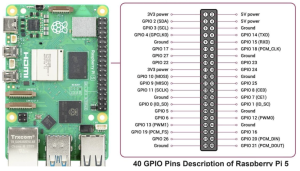
The Raspberry pi has a built-in library called python3-rpi.gpio, which initializes all the GPIO pins on the raspberry pi. The servo motor connects to the power, ground and a GPIO pin which receives the signal. The signal wire connects to a PWM GPIO pin, to allow for precise control over the signal that is sent to the servo. This pin can be plugged into GPIO12 or GPIO13. 

After this, I specify that the pin is an output and then initialize the pin. I use the set_servo_pulsewidth function to set the pulse width of the servo based on the angle from the audio localization output. 

Robot Neck to servo mounting solution: 

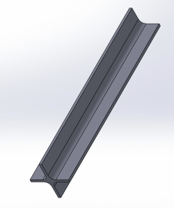
I designed a bar to mount the robot’s head to the servo motor while it’s housed in the robot’s body. 

The CAD for this design is as follows.

By next week, I plan to debug the audio triangulation and minimize the margin of error. I will also 3D print the mount and integrate it with the robot, and begin integration testing of these systems.


Team Status Report for 11/09/2024

Currently the biggest risk is to the overall system integration. Shannon has the WebApp functional, and Jeffrey has been working on unit testing individual parts of code such as RPS/DSI display. We will have to work on ensuring that the overall process is smooth, starting from ensuring the inputs from GPIO pins on the robot can be processed by RPi and then that the relevant information is sent to the Web App accordingly through WebSockets (so we can record information such as rock paper scissors game win/loss/tie results) and then that the WebApp displays the correct information based on what it received through WebSockets.

We will also need to perform some latency testing to ensure that this process is happening with little delay. (e.g. pausing from the robot is reflected promptly on the WebApp – WebApp page should switch from Study Session in progress to Study Session on break page almost instantly). 

Due to the display screen to RPi ribbon connector’s length and fragility, we have decided to limit the neck rotation to a range of 180 degrees. In addition, translational motion is also limited because of this. Therefore, by the interim demo, we only intend to have the rotational motion, and depending on the flexibility of the ribbon connector, we will limit or get rid of the translational motion. 

Interim demo goals:

Mahlet: 

  1. I will have a working audio localization with or close to the 5 degree margin of error in simulation. 
  2. I plan to have the correct audio input signals in each microphone, and integrate this input with the audio processing pipeline in the RPi.
  3. I will integrate the servo motor with the neck motion, and make sure the robot’s neck motion is working as desired.
  4. I will work with Shannon to ensure TTS functionality through gTTS and will do testing on pyttsx3 directly from RPi. 

Shannon: 

I aim to have the Study Session feature fully fleshed out for a standard Study Session, such that a user can 

  1. Start a Study Session on the WebApp (WebApp sends information to robot which starts timer)
  2. Pause it on the robot (and it reflects on the WebApp)
  3. When goal duration has been reached, the robot alerts WebApp and WebApp displays appropriate confirmation alert 
  4. User can choose to end the Study Session or continue on the WebApp (WebApp should send appropriate information to RPi) 
    1. RPi upon receiving information should either continue timer (Study Session continue) or display happy face (revert to default display)*
  5. At any point during the Study Session, user should also be able to end the Study Session (WebApp should send information to RPi)
    1. RPi upon receiving information should stop timer and then display happy face (revert to default display)*

* – indicates parts that Jeffrey is in charge of but I will help with

I also plan to have either the pyttsx3 library working properly such that the text-to-speech feature works on the WebApp, or have the gTTS feature working with minimal (<5s) processing time by pre-processing the user input into chunks and then generating mp3 files for each chunk in parallel while playing them sequentially.

For the RPS Game feature, I aim to ensure that the RPi can receive starting game details from the WebApp and that the WebApp can receive end game statistics to display appropriately.

Jeffrey: 

The timer code is able to tick up properly, but I have to ensure that pausing the timer (user can pause timer using keypad) is synced with WebApp. Furthermore, the time that the user inputs is stored in the Web App in a dictionary. I currently have code that is able to extract the study time from the duration (key in dictionary), and passes that into the study timer function, so the robot can display the time counting up on the DSI display. One mitigation is that we have the pause functionality on the DSI display itself, as opposed to GPIO input -> RPi5 -> WebApp. By using the touchscreen, we decrease reliance on hardware and makes it easier to debug via Tkinter and software.


RPS code logic is functional, but needs to be able to follow the flow chart from design report to go from confirm “user is about to play a game” screen -> display rock/paper/scissors (using Tkinter) -> display Win/Loss/Tie screen, or reset if no input confirmed. Our goal is to use the keypad (up/down/left/right arrows) connected to RPi5 to take in user input, and output the result accordingly. One mitigation goal is that we can utilize the touchscreen display of the DSI display, to directly take in user input on the screen to send to the WebApp. 

Integration goals: 

  1. The TTS will be integrated with the speaker system. Mahlet and Shannon are working on the TTS and Jeffrey will be working on outputting the TTS audio through the speaker. 
  2. For the Web App, Jeffrey needs to be able to take in user input from the Web App (stored as json), parse it, and send inputs to functions such as timer counting up, or the reverse, where a user action is sent to the WebApp i.e. user chose rock, and won that round of RPS. 


There have not been any changes to our schedule.

Mahlet’s Status Report for 11/02/2024

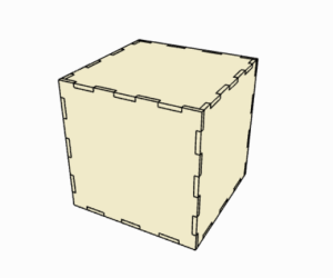
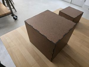
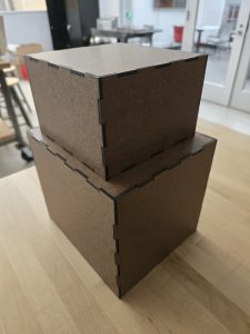
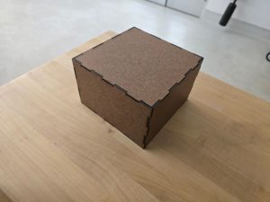
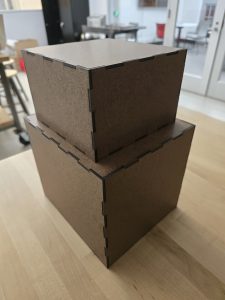
This week, I worked on the robot base structure building. Based on the CAD drawing we did earlier in the semester, I generated parts for the robot base and head that have finger edge joints. This allows for easy assembly. This way we can disassemble the box to modify the parts on the inside, and easily reassemble it back. The box looks as follows: 

During this process, I used the 1/8th inch hardwood boards we purchased and cut out every part of the body. The head and the body are separate, as they will be connected with a rod to allow for easy rotation and translational motion. This rod will be mounted to the servo motor.  As a reminder, the CAD drawing looks as follows.  

I laser cut the boxes and assembled each part separately. Inside of the box, we will be placing the motors, RPi, and speakers. The wiring of the buttons will also be placed in the body of the robot. The  results are as follows. The “feet” of the robot will be key inputs, which haven’t been delivered yet. The result so far look as follows: 


In addition to these, I worked on the TTS functionality with Shannon. I did some tests and found that the Pyttsx3 library works when running text input iterations outside of the webapp. The functionality we are testing is integrating the text input directly into the text to speech engine. This kept causing the loop error. When I tested the pyttsx3 in a separate file where I pass in various texts back to back by only initializing the engine once, it works as expected. 

We also worked on the gTTS library. The way this works is, it generates an MP3 file for the text file input and then reads that out once it’s done. This file generation causes a very high latency. For a thousand words, it takes over 30 seconds to generate the file. Despite this, we came up with plans to break up the file into multiple chunks and create the MP3 files in parallel, lowering the latency. This would get us to a faster TTS time, without having any issues similar to the pyttsx3 library. This is a better and fully functional alternative from our options, with a reasonable tradeoff of having slightly longer latency for longer texts for a reliable TTS machine.

In the coming week, I will be working mainly on finalizing the audio triangulation along with some testing, and begin integrating systems the servo system with the audio response with Jeffrey.

Team Status Report for 11/02/2024

The most significant risk is the TTS functionality. The hi library has been causing issues when data text input is directed from the WebApp directly. We have issues where a “run loop has already started” error occurs when trying to read new text after the first submission. As such, we have looked into alternatives, which includes Google TTS (gTTS). Upon trying gTTS out, we realized that while it does work successfully, it takes a significant amount of time to read long pieces of text aloud. Short texts with <20 words take an insignificant amount of time (2-3s) but longer pieces of text we tried such as 1000 words can take up to approximately 30s, and when we tried a standard page of text from a textbook, it took roughly 20s. These time delays are quite significant and is due to the fact that gTTS converts all text to mp3 first, and then the mp3 is played on the WebApp, whereas the previous TTS engine we wanted to use, pyttsx3, converts the text to speech as it reads the input text, and so performs much better. We also tried installing another TTS library, (just called the TTS python library) as a potential alternative for our purpose. We found that the file is very big, and when we tried installing it to our local computer it took hours and still wasn’t complete. We are concerned about the size of the library as we have limited space on the RPi. This library supports 1100 languages, and it takes very long to install. We plan to keep this in mind as a potential alternative, but as of now, gTTS library is the better option.

One potential risk with the DCI display to RPi5 connection is the fact that we aren’t able to connect via the HDMI port. Our goal is to use the MIPI DSI port. From the Amazon website, there is an example video of connecting the DCI display directly to the RPi5, to ensure that the display is driver free and compatible with the RPi signal (The RPi OS should automatically detect the display resolution). The display is 800×480 pixels, if our port isn’t working, we can directly set the resolution to the screen via code: hdmi_cvt = 800 480 60 6. This represents the horizontal resolution and vertical resolution in pixels, the refresh rate in hertz, as well as the aspect ratio, respectively. 

As an update to our previous report concerns about not having built the robot base, this week, we have managed to laser-cut the robot base out of wood. Since the base is designed to be assembled and disassembled easily, it allows for easy parts access/modification to the circuit. For photos and more information about this, refer to Mahlet’s Status Report.  

There are no changes to our schedule.

Mahlet’s Status Report for 10/26/2024

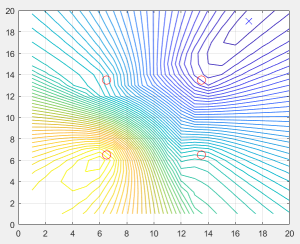
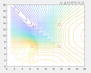
This week I worked on the forward audio triangulation method with the real life scale in mind. I limited the bounds of the audio source to 5 feet from each side of the robot’s base and placed the microphones at a closer distance. I accounted for accurate values in units to make my approximation possible. Using this, and knowing the sound source location, I was able to pinpoint the source of the audio cue. I used a smaller scale to go over the grid dimensions to have a closer approximation. This is to allow low inaccuracies in the direction that the robot is going to turn to. 

I randomly generate the audio source location, and below are some of the simulations for this.  The red circles denote the source of audio and the cross indicates the audio source.

After this,  I pivoted from audio triangulation and focused on tasks such as setting up the RaspberryPi, doing tests for the TTS with Shannon and learned  about the WebSocket connection methodology. I joined Shannon and Jeffrey’s session when they discussed the WebSocket’s approach and learned about it

During setting up the RaspberryPi, I ran into some issues with it, while trying to SSH to it. Setting up folders and the basics however went well. One task for next week is to reach out to the department to get more information about prior connections with the raspberry pi. It is already connected to CMU Secure as well as CMU devices networks, however it doesn’t seem to be working with the CMU device network. I tried registering the device to CMU Devices, but it seems like it has been registered prior to this semester. I aim to figure out the issue with SSH-ing to this device over the next week. However, we can still work with the RPi using a monitor, so this is not a big issue. 

After this, I worked on Text-To-Speech along with Shannon, and worked on the pyttsx3 library. We intended so that the WebApp reads various texts back to back through the text/file input mechanism. The library works by initializing a text engine, and uses the function, engine.say(), to read the text input. This works when running the app for the first time. However after inputting data for the second time and onwards, it gets stuck in a loop. The built-in engine.stop() function requires multiple instances of initialization of the text engine, which causes the WebApp to lag. As a result, Shannon and I have decided to look into more TTS libraries that can be used for python, and also we will try testing the TTS directly on the RPi instead of the WebApp first.

My progress is on track, the only setback is the late arrival of ordered parts. As described in the team weekly report, I will be using the slack time to accommodate for progress with assembling the robot, and integrating systems. 

Next week I will be working on finalizing the audio triangulation, work with Shannon to find the optimal TTS functionality and work with Jeffrey to build the hardware.

Team Status Report 10/12/2024 / 10/19/2024

The most significant risk as of now is that our team is slightly behind schedule and should be working on completing the build of the robot base and individual component testing along with the implementation using the RPi. To manage these risks, we will use some of the slack time delegated to catch up on these tasks and ensure that our project is still overall on track. Following the completion of the design report, we were able to map the trajectory of each individual task. Some minor changes were also made to the design, with the removal of the todo-list feature on the WA because it felt non-essential and was a one-sided feature on the WebApp, and the neck of the robot having only rotational motion response along the x-axis for audio cue, and y-axis (up and down) translation for a win during RPS Game. We decided to change this because we wanted to reduce the range of motion for our servo horn that connects the servo mount bracket to the DCI display. By focusing on the specified movements, our servo motor system will be more streamlined and even more precise in turning towards the direction of the audio cues.

Part A is written by Shannon Yang

The StudyBuddyBot (SBB) is designed to meet the global need for accessible, personalized learning by being a study companion that can help structure/regulate study sessions  and incorporate tools like text-to-speech (TTS) for auditory learners. The accompanying WebApp to the robot ensures that it can be accessed globally by anyone with an internet connection, without requiring users to download or install complex software or paying exorbitant fees. This accessibility factor helps make SBB a universal solution for learners from different socioeconomic backgrounds.

With the rise of online education platforms and global initiatives to support remote learning, tools like the StudyBuddyBot fill a crucial gap by helping students manage their time and enhance focus regardless of geographic location. If something similar to the pandemic were to happen again, our robot would allow students to continue learning and studying from the comfort of their home while mimicking the effect of them studying with friends. 

Additionally, as mental health awareness grows worldwide, the robot’s ability to suggest breaks can help to address the global issue of burnout among students. The use of real-time interaction via WebSockets allows SBB to be responsive and adaptive, ensuring it can cater to students across different time zones and environments without suffering from delays or a lack of interactivity.

Overall, by considering factors like technological accessibility, global learning trends, and the increasing focus on mental health, SBB can address the needs of a broad, diverse audience.

Part B is written by Mahlet Mesfin

Every student has different study habits, and some struggle to stay focused and manage their break times, making it challenging to balance productivity and relaxation. Our product, StudyBuddyBot (SBB), is designed to support students who face difficulties in maintaining effective study habits. With features such as timed study session management, text-to-speech (TTS) for reading aloud, a short and interactive Rock-Paper-Scissors game, and human-like responses to audio cues, SBB will help motivate and engage students. These personalized interactions keep students focused on their tasks, making study sessions more efficient and enjoyable. In addition, SBB uses culturally sensitive dialogue for its greeting features, ensuring that interactions are respectful and inclusive.

Study habits vary across different cultures. For example, some cultures prioritize longer study hours with fewer breaks, while others value more frequent breaks to maintain focus. To accommodate these differences, SBB offers two different session styles. The first is the Pomodoro technique, which allows users to set both study and break intervals, and the second is a “Normal” session, where students can only set their study durations. Throughout the process, SBB promotes positive moral values by offering encouragement and motivation during study sessions. Additionally, the presence of SBB creates a collaborative environment, providing a sense of company without distractions. This promotes a more focused and productive study atmosphere.

Part C was written by Jeffrey Jehng

The SBB was designed to minimize its environmental impact while still being an effective tool for users. We focus on SBB’s impact on humans and the environment, as well as how its design promotes sustainability. 

The design was created to be modular, so a part that wears out can be replaced as opposed to replacing the whole SBB. Key components, such as the DCI display screen and the microcontroller (RPi), were selected for their low power consumption and long life span, to reduce the need for replacement parts. To be even more energy efficient, we will implement conditional sleep states to the SBB to ensure that power is used only when needed. 

Finally, we have an emphasis on using recyclable materials, such as acrylic for the base, and eco-friendly plastics for the buttons, that reduce the carbon footprint of the SBB. By considering modularity, energy efficiency, and sustainability of parts, the SBB can be effective at assisting users and balancing its functionality with supporting these environmental concerns.