

18-796 Multimedia Communicaions:
Coding, Systems and Networking
Final Project Report
Group members: Ching-Kai
Huang Wing Ho Leung
Implementation of a speech codec based
on coding of speech at 8 kbit/s
using conjugate-structure algebraic-code-excited
linear-prediction (CS-ACELP)
[ITU-T Recommendation G.729A]
Our goals for the final
project is to implement the encoder and decoder following the G.729A recommendation
except for some quantization modules and bit stream compliance.
We took .wav files that
is sampled at 8000 Hz using 16-bit linear PCM. The encoding process is
done every 10ms frame or 80 samples. For the preprocessing stage, the samples
are high passed with cut-off frequency of 140 Hz and scaled down by 2.
A total of 240 samples are buffer for windowing and autocorrelation computation.
The autocorrelation coefficients are used to calculate the LP filter coefficients
using the Levinson-Durbin algorithm. The LP filter coefficients are converted
to Line Spectral Pair (LSP) coefficients. LSP coefficients are converted
back to the LP filter coefficients, which is just the reverse process of
the conversion from LP to LSP. This module is exactly what the decoder
will need in order to convert the LSP coefficients to LP coefficients.
We decided not to implement the LSF quantization module because we did
not have the codebook information when we designed our system.
The open-loop pitch delay is calculated first for each frame.
Then the closed-loop pitch delays for each subframe are estimated around
the open-loop pitch delay using the correlation function calculated from
the pre-processed signal. The adaptive code vector is then obtained by
interpolating the excitation signal around the closed-loop pitch delay.
Next, the fixed code vector which consists of 4 pulses are obtained by
searching the codebook and selecting the one whch maximizes the correlation
term normalized by it's energy. The fixed code vector is passed to a pitch
pre-filter if the closed-loop pitch delay is small. The adaptive and fixed
codebook gains are calculated and the excitation signal and the states
of the weighting filter are updated.
The modules of the decoder are similar to the inverse
of the encoder, and even simpler. The idea is that based on the encoded
parameters, we reconstruct both the adaptive and fixed code vectors, then
scale them with the adaptive and fixed codebook gains which are also parameters
from the encoder. Then we calculate the excitation signal by adding the
scaled adaptive and scaled fixed code vector. On the other hand, we also
find the LP coefficients from the LSF parameters. We use Linear Prediction
to reconstruct the speech signal using the excitation signal and the LP
coefficients. Then the signal is passed to the post-processing stage to
improve the speech quality.
The following table shows our parameters to be transmitted
for each frame:
|
Description
|
Symbol
|
Bits
|
|
Line Spectral Frequency
|
w1
|
32
|
|
Line Spectral Frequency
|
w2
|
32
|
|
Line Spectral Frequency
|
w3
|
32
|
|
Line Spectral Frequency
|
w4
|
32
|
|
Line Spectral Frequency
|
w5
|
32
|
|
Line Spectral Frequency
|
w6
|
32
|
|
Line Spectral Frequency
|
w7
|
32
|
|
Line Spectral Frequency
|
w8
|
32
|
|
Line Spectral Frequency
|
w9
|
32
|
|
Line Spectral Frequency
|
w10
|
32
|
|
Parity bit for pitch delay
|
P0
|
1
|
|
Pitch delay 1st subframe
|
P1
|
8
|
|
Pitch delay 2nd subframe
|
P2
|
5
|
|
Fixed codebook 1st subframe
|
C1
|
13
|
|
Signs of fixed codebook pulses 1st subframe
|
S1
|
4
|
|
Fixed codebook 2nd subframe
|
C2
|
13
|
|
Signs of fixed codebook pulses 2nd subframe
|
S2
|
4
|
|
Adaptive codebook gain for 1st subframe
|
gp1
|
32
|
|
Fixed codebook gain for 1st subframe
|
gc1
|
32
|
|
Adaptive codebook gain for 2nd subframe
|
gp2
|
32
|
|
Fixed codebook gain for 2nd subframe
|
gc2
|
32
|
|
Total
|
|
496
|
Table 1 Description of transmitted parameters
Without coding, 16 bits
would be required to represent each sample and therefore 1 frame which
corresponds to 80 samples requires 16x80 = 1280 bits. From the above
table, it can be seen that 496 bits are used to code 1 frame. This gives
a compression ratio of 2.58. We haven't made use of the VQ tables for coding
line spectral frequencies as L0, L1, L2 and L3;
and haven't coded the codebook gains as GA1, GB1, GA2,
and GB2. Otherwise each frame will only require 80 bits and the
compression ratio would become 16.
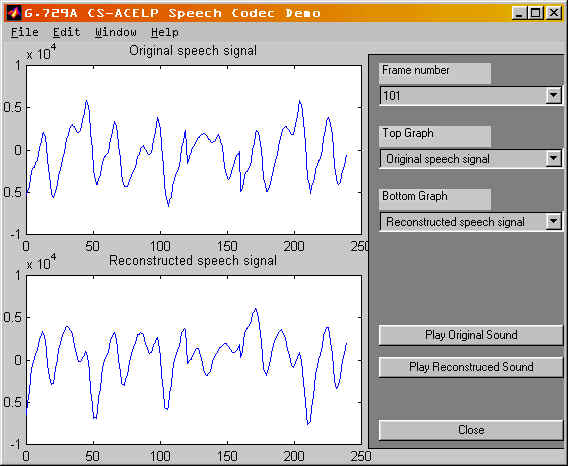
We have modified our
MATLAB graphical user interface built before the midterm. This user interface
is enhanced to be capable of displaying different signals of different
frames. The signals generated from the encoder to be displayed include
the original speech signal, the preprocessed signals, the LP residual signal,
the adaptive and fixed code vectors, the excitation signal and Line Spectral
Frequencies. The signals generated from the decoder to be displayed include
the reconstructed LP residual signal, the reconstructed adaptive and fixed
code vectors, the reconstructed excitation signal, the signal before postprocessing
and the reconstructed speech signal. Two different graphs can be viewed
at a time in order to facilitate comparison. In addition, we can listen
to the original and reconstructed .wav files using our MATLAB user interface
in order to evaluate the quality of the reconstructed speech. The following
figure shows a snapshot of our MATLAB graphical user interface:
The source codes for
this project are:
encoder.zip - program
source code to encode a WAV file
decoder.zip - program
source code to decode back to a WAV file
get_signal.zip - program source
code to get intermediate signals for both the encoder and the decoder to
be used by the MATLAB demo
demo.zip
- demo directory which contains the EXE files for the above programs, the
MATLAB demo files, and some test WAV files.
also contains a readme.txt file to help explaining how to use the demo
programs.