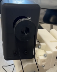
This week, I addressed an earlier issue that arose as we assembled our project which was that the calculation for the timing belt was not correct. I designed and 3D printed a tensioner out of spare PLA to provide more tension to the belt and allow the belt to maintain engagement with the pulleys under higher loads. This was sufficiently addressed and leaves room for more or less tension to be added since it is only layers of masking tape that comprise of the roller’s volume.
I also began gathering materials that will help create the ramp soon. In the coming week, I will need to reprint some modules with the servo components, and use scrap parts in order to create the ramp for our project. However, the goal for me is to get the entire mechanical system ready for integration and testing for the team.
This week I worked on interfacing with the Oak-D SR in addition to setting up CUDA on the Jetson Nano. The Oak-D camera gave us trouble during the interim demo, leading us to temporarily swap it for a more generic webcam. I managed to get it working after using a high bandwidth USB 3.0 to USB type C, whereas I was previously using a generic USB type C cable. As of right now I have only managed to run the DepthAI Viewer program provided by Luxonis, which demos the camera on a stock YOLOv8 model.
Regarding the Jetson, inference on CUDA was not working initially as mentioned in the Team Status Report. As it turns out the version of OpenCV installed on the Jetson by default does not have CUDA support. While I tried to install the necessary packages to enable it prior to the demo, I did not see much success. As building the package from scratch was obnoxious and often riddled with compatibility issues, I opted to instead reflash the Jetson with a firmware image I found on GitHub that had all the prerequisites pre-installed. Following the reflash I confirmed that CUDA was enabled before reinstalling Wi-Fi compatibility and the Arduino IDE for interfacing with the actuators.
Next week, I hope to integrate the Oak-D SR camera into the cohesive system instead of the webcam we have been using thus far. The Oak-D does have promising depth perception which can be used to determine the front-most object in the belt should our current approach that uses the YOLO bounding boxes fail. As I got CUDA working, I am not particularly interested in running our YOLOv5 mode natively on the camera as that may be riddled with compatibility issues (the demo does have YOLOv8 instead of v5).
Regarding verification plans for the object detection and classification sub-system, I want to re-run the program used for the interim demo to begin benchmarking the inference speed with GPU acceleration as CUDA works now. This corresponds to the “System runs inference to classify item < 2 seconds” requirement mentioned in the Team Status Report. Additionally, I want to benchmark the model’s current classification accuracy to determine if additional fine-tuning is necessary. As outlined in the design presentation, this will be done through 30 trials on assorted objects, ideally representing the classes of plastic, paper, metal, and waste equally. The objects will be moving on the belt to better simulate the nature of the final product.
Potential Risks and Risk Management Having started on the build, actuators programming, user interface, and model fine-tuning, we cannot determine any major risks at the moment. While building the conveyor belt part, we realized that the rubber sheet purchased was only good for lining up the rollers once, meaning failure to do so successfully would require purchasing another roll. We have, therefore, been careful when applying the roller for the interim demo. Regardless, we have enough money in our budget to purchase another sheet of rubber should the need arise. While testing the model’s inference in real time, we also noticed that the model performed best at a certain elevation and angle with respect to the object being detected, likely due to how the dataset utilized was oriented. This means that other viewings of the objects on the belt would be detrimental to the accuracy of our detection. We, therefore, are optimizing our camera’s position on the overall product such that it provides optimal inference results.
Overall Design Changes No major design changes have been made since the last Team Status Report. Schedule We are on track with the schedule based on our progress for the interim demo.
Progress Update Over the week, we made progress on the mechanical side of things by starting to assemble the conveyor belt. We integrated the motor with the motor driver and were able to test out the setup. We aim to have the belt assembled and ready by the interim demo, and a separate working set up of the sorting and object detection mechanism
This week, I did the setup for the web application that we plan on using to control the speed of our conveyor belt system. We will be using Django to run this web application. I also looked into the different modules I will require to be able to get live video feed from the camera integrated into this webpage. At the moment, there is a rough sliding bar on the website. Over the weekend, I plan on working on the design and feeding inputs to the page to the motor driver.
I also found a useful tutorial on implementing video streaming from the OAK-D Camera with OpenCV and Flask modules, which I will be experimenting with over the next few days.
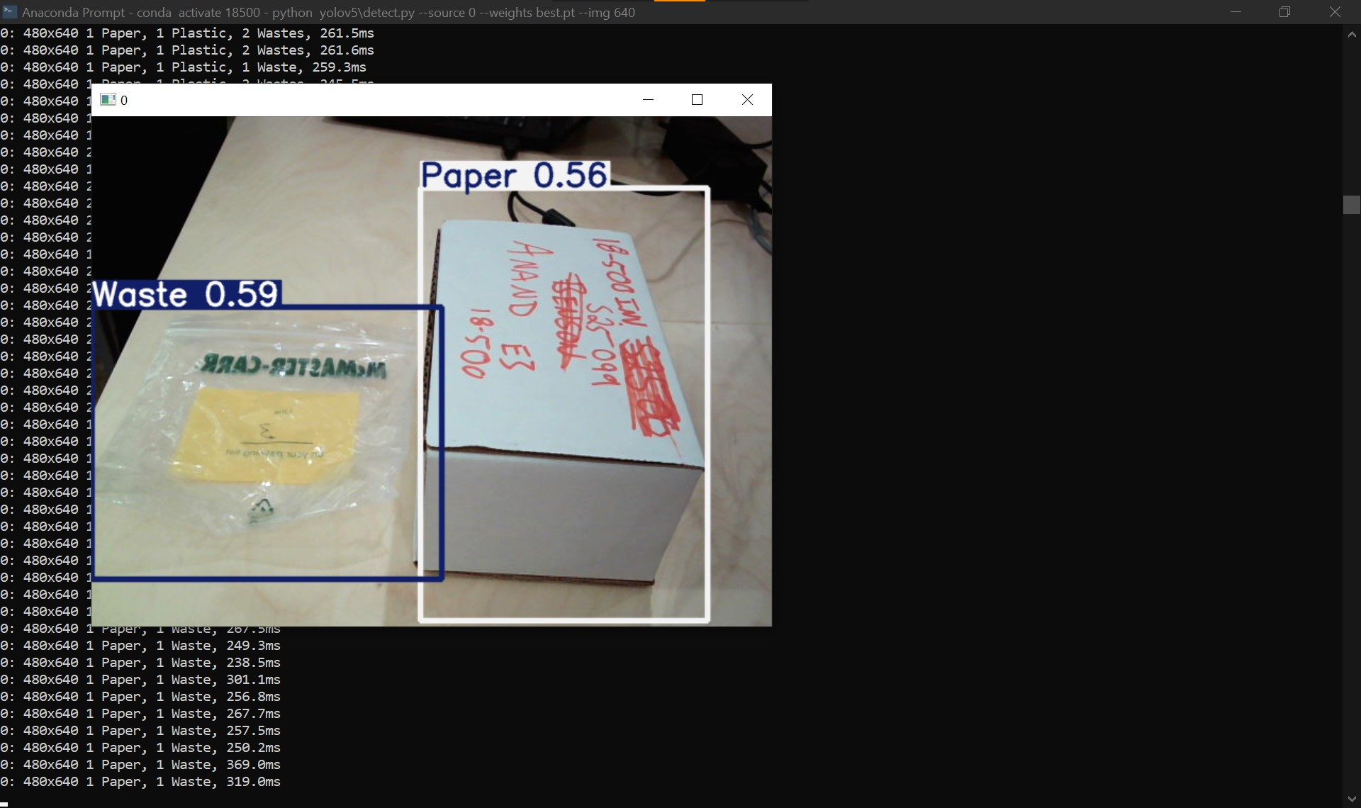
This week I primarily worked on improving the YOLO model’s performance through additional fine-tuning in addition to testing it in a real-time setting through a webcam attached to my laptop. Compared to a few weeks ago, the model is performing better in classifying paper, plastic, metal, and waste (general trash). However, it still struggles with classifying glass particularly, most likely as there are not many images with glass objects in them in the TACO dataset. Additionally, through testing the model’s inference on a live camera viewing, I have noticed that it performed best at an elevated angle that looked down on the objects for classification. I believe that to be case based on the images in the TACO dataset, which were captured at a similar perspective. By that, I experimented with multiple angles and elevations with respect to the objects to determine the best one, which we hope to deploy in the conveyor belt itself.
Inference running live on assorted objects
To train the model more efficiently, I stopped using Google Colab and set up an environment that trains on John’s home desktop as it does have hardware comparable to an NVIDIA T4, which has been working great so far. Special thanks to John for offering!
Additionally, I was helping the team out with putting everything together for the intermin demo.
Going beyond the interim demo, I hope to improve the model’s precision and recall further in all the object classes. This may need some data augmentation for certain classes, particularly glass. I also hope to test the model’s performance on other datasets not used for training.
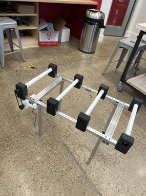
This week, I finished manufacturing the major hardware components we were planning to 3D print, so I was able to begin putting together our more major hardware components. With the assistance of the others, I was able to nearly fully assembly the conveyor belt today. Shown below is the primary structure of the conveyor belt and its roller structures which might stick with us to our final design. Otherwise, our plans remain the same, if not pushed slightly back since we are progressing a little slower than ideal.
This week, I manufactured all of the materials we would need to begin assembling. Attached is an image of all the printed parts we will need to assemble with our metal structural components. I will proceed with assembling all the material quickly so the team can begin testing the overall system.
We have finished 3D printing the necessary components this week though we anticipate issues that may lead to reprinting. We will be inspecting each printed component this weekend and reprint at the Roboclub facilities on campus as needed. Running out of 3D printing filament is the least of our concerns at the moment as our Amazon purchase bundled four rolls together, whereas we are only using one at the moment.
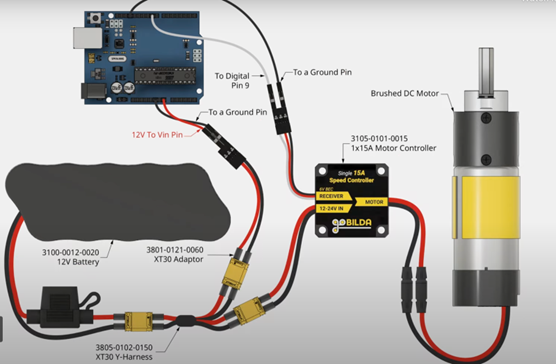
Additionally, upon inspecting the Arduino schematic we noticed that we will also have to plug in our DC power source (supplying 12V) to the Arduino’s “Vin” port for power. Initially we feared that the supplied voltage would overwhelm the Arduino but upon closer inspection, it would appear the Arduino is capable of withstanding a maximum of 12V. Regardless, as the voltage we are supplying is the maximum, we are considering powering the Arduino using the data port with the Jetson to circumvent potential pitfalls. The Arduino will still be grounded with the remaining electronics.
Furthermore, we believe the alligator clips found on campus are incapable of withstanding the higher voltage and current necessary for powering the DC motor driver. Therefore, we will be soldering higher gauge wire onto the purchased male to female wire.
Overall Design Changes
There have been no major design changes since our last status report. We will likely be adding a breadboard to better manage the wiring of the actuators with the Arduino, though the overall wiring should remain the same.
Schedule
Currently, there are no major updates to our schedule. However, we have updated it to indicate our progress on ongoing tasks.
This week, we were able to drive the servo with the Arduino 5V with hardcoded classification signals.
The goal is to establish communication with all devices (Arduino, Jetson, Motor, Servo) by the end of the coming week. Over the weekend, we plan to integrate the classification signals into this infrastructure to drive the components accordingly in time for the interim demo.
Wiring with an external power supply, which needs to be tested
Additionally we have started work on the mechanical build of the project. We sliced the metal parts in TechSpark and began 3D printing the necessary components. We hope to continue assembly to have a partially functional product in time for the interim demo.
Conveyor belt 3D printed components
Regarding the model, we have started fine-tuning this week. We are utilizing the training files pre-defined by Ultralytics for YOLOv5 (yet another benefit to adapting a YOLO model), which comes with some neat visualizations as shown below. We are fine-tuning our model to improve its performance with regards to not only accuracy but also reducing false results, which can be more accurately judged via the precision and recall metrics provided by the script.
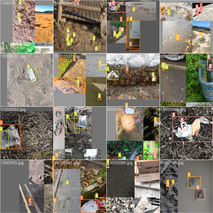
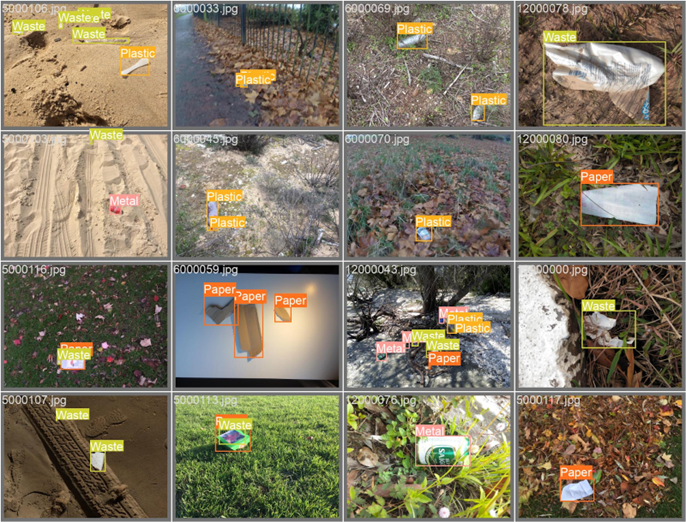
Batch predictions made during training based on the defined class numbers (e.g. 1 = Metal)Batch predictions made during validation, now showing labels by name
This week I have been fine-tuning the pre-trained YOLO model we initially used as a proof of concept. I used the training files included in the YOLOv5 repo by Ultralytics, which provide neat prediction and losses visualizations. I am monitoring the model’s progression and visual results on my linked WandB account. Dataset wise, I used the TACO dataset with revamped labels which I defined last week. Before using the dataset though I had to split it by training / validation / testing. At the moment, 70% of the dataset is used for training, 20% is used for validation, and 10% is used for testing, where the original dataset contains approximately 1500 images. The shuffling of images and splitting was done using a Python script I wrote, similar to the one used for relabeling the .txt label files. The final addition to the dataset was writing a custom yaml file following Ultralytics formatting to specify the classes and data locations. Putting it all together, I assembled a Python Notebook file on Google Colab running on a T4 GPU for training, which seems to train efficiently as a single epoch takes under 5 minutes with my current settings.
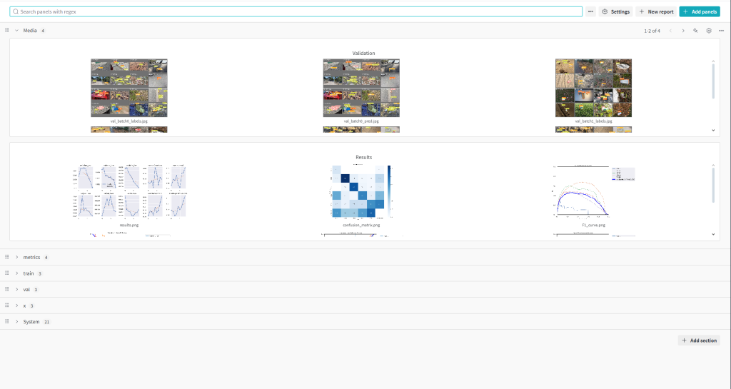
WandB page for a single training instance.
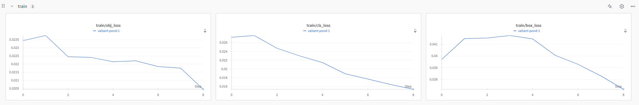
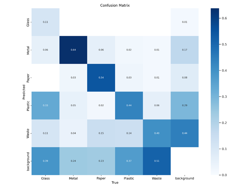
In terms of evaluating our fine-tuned model’s performance, the current script provides both object loss and classification loss for training and validation. Furthermore, the script provides precision and recall which provide further judgement beyond accuracy. Following the conclusion of training, validation, and testing, a confusion matrix is produced, also shedding light on performance with respect to ground truth and false predictions. Following training on a few epochs, we are already seeing some improvements in terms of reducing the losses. Of course, judging the model’s overall performance is also possible through inspecting the intermediary predictions the model gives for both training and validation.
Training graphs for a sample run of 10 epochs.Confusion matrix of said sample run.Batch predictions made during validation, giving the labels by name
Next week, I hope to continue training to obtain a satisfactory model following the evaluation metrics provided by the Ultralytics script. Furthermore, I aim to maybe use a platform other than Google Colab for training as GPU resources is subject to availability, unless I pay for a credit and/or a Pro account. I am considering using the ECE machines as they also do have T4 GPUs though the process can be finnicky from what I have been told.
This week, I wrote the infrastructure to get the Arduino to communicate with the servo for our sorting mechanism. I drove the servo with 5V from the Arduino. However, I noticed that the reason that worked was because the no-load current of the Arduino was 190mA. With a load (which we will definitely have when we integrate the servo into the mechanical build of our product), our stall current goes up to 2000mA, which is way more than the Arduino can safely handle. Because of this, I will need to power the servo with an external power supply, which I intend to experiment with in the following week. I also wrote the infrastructure to drive the motor through the motor driver and Arduino however, this also needs an external power supply due to the excessive current draw. In addition to this, I plan on starting the UI powered by the Jetson and establishing communication with the motor.