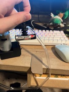
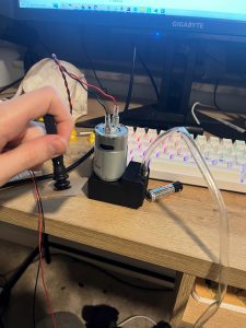
Teddy’s Status Report for 3/29

This week was spent doing work for the conveyor belt, updated gantry frame, and the end-effector. I was able to construct a rough conveyor belt when the materials arrived, such that the cloth has enough tension where it rolls when the bars it is wrapped around rotate. I spent some time working out how the new gantry frame will be build using the new aluminum extrusions, with the plan being to cut the rods sometime next week for assembly. I was also able to finish the design of the end-effector by attaching a solenoid to the end-effector such that a hole is plugged and unplugged to release the objects grabbed by the suction end-effector. I plan to attach it to the gantry tomorrow so that it is ready in time for demo.

Next week I hope to rebuild the frame and attach a stepper motor to the conveyor belt so that it is able to turn when commanded by the Arduino. I also hope to start the movement estimation code so that the gantry can move to the object’s location given that it is moving at a constant speed after detection. I am on schedule.

Team Status Report for 3/29

What are the most significant risks that could jeopardize the success of the project? How are these risks being managed? What contingency plans are ready?

One of the most significant risks currently is that the stepper motors will not have enough speed to complete the pickup sequence in 8s. We have had to run the gantry slower than the maximum setting as the frame currently isn’t well-built enough to handle the stresses. We plan to address this by changing the frame to using aluminum extrusions instead of aluminum angles. One other risk is that the stereo camera might not be accurate enough to sense the depth for accurate placement of the end-effector on the trash items. Currently our contingency plan for this is to use a pressure sensor to detect when the end-effector touches the object.

Were any changes made to the existing design of the system (requirements, block diagram, system spec, etc)? Why was this change necessary, what costs does the change incur, and how will these costs be mitigated going forward?

Other than the change to the frame mentioned above, there are no planned changes to the existing system. This change was necessary as parts of the gantry were bending and buckling during the gantry’s movements. Replacing the aluminum parts costs around $60, which is not much of a problem since after the purchase we still have around $250 of budget remaining.

Provide an updated schedule if changes have occurred.

There are no schedule changes as of now.

Teddy’s Status Report for 3/22

This week was spent working on getting the vacuum end-effector to work. After some testing and design changes, I was able to get the end-effector to the point where it is able to pick up all 4 types of recycling consistently. I still need to add a release mechanism, which should just be a solenoid which opens and closes a hole in the air flow. I’ve designed and 3d-printed a part that should fit onto the end of the z-axis rack. I’ve also started looking into the stereo camera and the repository that comes with it to get the depth map from the camera. I also spent some time this week ordering parts, including the belt for the conveyor belt, silicone tubing for the vacuum pump, and aluminum extrusions for the gantry. The current construction of the gantry’s frame is hypothetically sufficient, but there seems to be severe wobbling, so switching from aluminum angles to aluminum extrusion should hopefully solve the problem.

Next week, I hope to attach the vacuum pump and suction end-effector to the gantry, get the conveyor belt cloth attached, get the depth map from the camera, and if time allows replace the aluminum angles with aluminum extrusion. I am behind schedule but I am catching up to what was planned.

Teddy’s Status Report for 3/15

Most of the time spent this week was on expanding and reinforcing the gantry to compensate for the sag caused by scaling up the design of the 4xidraw. I was able to construct a large frame around the conveyor belt in order to provide a mount for the 4xidraw. I then had to redesign some of the parts of the 4xidraw so that there would be no sag; this involved making one of the rods slide along the frame so that it supported the end-effector. I was also able to print out the rack so that the rack-and-pinion z-axis movement was complete. I’ve also begun testing the vacuum pump with the suction cup. It seems to be able to pick up flat, non-porous objects like plastic consistently, however it does not work as well with porous materials like paper.

Next week I plan to start working on programming the xy movement and will hopefully finish a fleshed out design of the vacuum end-effector. I am slightly behind schedule as I didn’t anticipate the rebuilding of the gantry to take as long as it did.

The picture of the current gantry is shown below:

Teddy’s Status Report for 3/1

Over the last two weeks, I worked on constructing the gantry as well as the frame that holds it. I was able to construct the 4xidraw part of the gantry since all of our parts had finished arriving. I was then able to print, assemble, and attach the z-axis to the gantry. Currently, the parts required for the z-axis movement are assembled, but the end-effector is not attached, since we are still waiting for the vacuum pump and the relays to arrive. There is an issue in that the z-axis can’t extend very far away from the gantry, as the weight causes the rods to sag. In order to remedy this, I’m planning on attaching a bar horizontally onto the part where the z-axis attaches to the rest of the gantry, which will rest on two other bars so that the front does not sag. A picture of the current gantry is shown below.

I am a little behind schedule, partly due to delays in the shipping of the gantry parts as well as the end-effector parts. I plan to fix the sagging issue on the gantry next week, as well as hopefully get the electronics and the code for the 4xidraw working.

Team Status Report for 2/22

What are the most significant risks that could jeopardize the success of the project? How are these risks being managed? What contingency plans are ready?

Currently, the most significant risk to the success of the project is the end-effector design. It has to be able to adapt to a wide range of surfaces, and there is a decent change that our current design might not be enough to achieve that. We recently decided that we would be adding a vacuum pump to the end-effector in order to create a better suction for items that are porous, have irregular surfaces, and/or heavy. If this doesn’t work, we will pivot to a claw-like end effector.

Another risk to our design is our current depth estimator. Right now, we plan to use a stereo camera in order to obtain the height of the objects so that the end-effector knows how far down it should travel. If there are problems with the resolution or the reliability of the depth reading that we get from this camera, it would prevent the gantry from moving to the correct location. The current contingency plan is to add a pressure sensor onto the end-effector if the readings end up being too coarse or unreliable.

Were any changes made to the existing design of the system (requirements, block diagram, system spec, etc)? Why was this change necessary, what costs does the change incur, and how will these costs be mitigated going forward?

We’ve added a vacuum pump to the end effector, as from some initial testing the suction cup end effector is not of adequate consistency when it comes to picking up some basic trash items. This does not incur any costs, except to our budget.

Provide an updated schedule if changes have occurred. 

No schedule changes have been made.

Teddy’s Status Report for 2/22

The bulk of the time this week was spent designing parts for the z-axis movement/end effector as well as working on making a functioning conveyor belt. I’ve created CAD models for the rack and pinion movement, and have started assembly of the parts. I received multiple parts that had been ordered, including the suction-cup attachment for the end effector, and after some testing, decided that it would be necessary to actively pull a vacuum instead of having just passive suction. After some research, I was able to find a way to pull a vacuum (with minimal noise so it doesn’t interfere with other demos) and have ordered the parts for the vacuum attachment. I’m currently working on designing the 3d printed parts that will attach the vacuum and the end effector to the rack and pinion system. Additionally, I was able to construct a frame for the conveyor belt out of 3d printed parts and aluminum (image of frame is shown below). Currently working on designing a basic belt that will be the surface that the trash will rest on.

I am currently a little behind schedule, as the switch to an actively-pulled vacuum requires additional design work. I’m planning on finalizing the design of the z-axis/end effector and working on the Arduino code for the gantry xy movement for the over the next week.

Teddy’s Status Report for 2/15

This week, I started the design of the z-axis movement and the vacuum end effector. I did a bit of research on methods of vertical linear motion, and settled on a rack-and-pinion based system driven by a stepper motor. I’ve started to create and assemble the CAD files which will be printed out when the design is fully fleshed out. The relevant parts for the end-effector have also been ordered, and added to the BOM in a new section. I spent a few hours working with the stereo camera, and discovered that it has its own python wrapper which should hopefully integrate well into our other code.

Additionally, I printed out all of the 3d printable parts for the 4xidraw gantry for the xy movement. 

Currently, I am a little bit behind schedule, as I expected the parts we ordered to come in earlier so I could start designing around them.

Teddy’s Status Report for 2/8

Most of the week was spend finding parts to purchase for the xy part of the robot gantry. Tried to keep costs low while not sacrificing too much in quality where it counts (e.g., spent more on the rods for guiding the movement of the end effector in the xy plane, since they needed to hold up to tighter tolerances).  Also had to do some small design changes to the 4xidraw design since our gantry will be significantly larger.  Additionally did some research on an adequate vacuum end-effector and possible ways that the gantry could have motion in the z-axis.

Link to the BOM for the xy part of the gantry is here: https://docs.google.com/spreadsheets/d/1N34-p-gZ5hg3E984jC0rKGtYfBRqveXMVGyWjgI6nZA/edit?usp=sharing

Plan for next week is to start designing the z-axis movement and the end effector, as well as to start 3D printing parts.

Currently everything is on schedule.