
General update
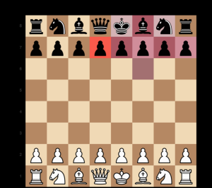
- In order to ensure we have a complete demo-able system, we have switched the gaze tracking from the physical 3D plane to a 2D screen. Liam implemented and added a calibration to this to increase accuracy. He is working in parallel on testing and validating this implementation, and a hail-mary effort to get 3D gaze tracking to the required accuracy.
- In testing, Trey was finally able to get consistent magnet movement of the pieces by lowering the lid on the enclosure. He also made the discovery that sanding down the base of the pieces to make them smoother leads to better magnet movement.
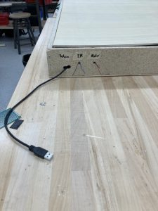
- Tarek continued verifying and validating the many parts of the embedded controller subsystem. He also used a new high-power NMOS to ensure the Arduino can turn the electromagnet on and off.
- Tarek and Liam have individually written the communication scripts to integrate their subsystems, and only testing remains.
Potential risks and risk management
- While Trey made great attempts and progress on getting consistent magnetic piece movement, the king and queen are still prone to failure due to their increased weight. Integration and user testing will reveal wether this meets our benchmark.
- 3D gaze tracking is unlikely at this point, but the identified and implemented alternative is working and suitable given the specifications.
Overall design changes
- 3D gaze tracking to 2D eye-gaze-tracking.
Schedule
We are on track to finish everything by the deliverable dates.
TESTING DONE
- Tarek has written scripts for every stand-alone component in the embedded controller and used them to validate the components, which all performed according to the specs.
- Trey tested magnetic piece movement to ensure consistent piece pickup by the magnet, in doing so he found that lowering the height of the lid on the enclosure and sanding down the base of the pieces better results could be achieved.
- Liam performed manual tests on the new gaze-tracking UI to ensure it conforms according to the specs. He is currently working on quantitatively measuring this, but so far, the system seems to meet the desired accuracy.
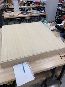
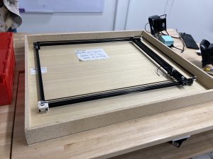 2. Basic Magnet Testing (4hr): Due to the external delays for cutting the wood, we had to wait to fully test some of the electromagnet functionality. However, in the meantime, we did some basic tests by propping up a piece of wood above the electromagnet at the same height as the box lid. We placed a magnet on top of the wood and turned the magnet on, then moved the gantry using the step motors. We found that the magnet moved smoothly in each direction. I also used some chess pieces that Tarek 3D printed, placed them on top of the magnet, and tested again to determine that we could move these chess pieces around the wood with the electromagnet. That was exciting to see!