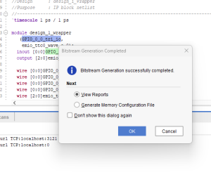
This week I focused on establishing the hardware and software foundation for our two-piston balancing platform. I created a Vivado block design for the Ultra96 board with SPI interface configuration, successfully implementing the design and generating the necessary files for PetaLinux integration to prepare for the software development phase.
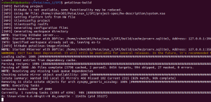
On the software side, I built a custom PetaLinux image with SPI drivers enabled, modified the device tree to properly configure the SPI interface, and created the necessary boot files for the Ultra96 board. For communication testing, I established a serial connection for debugging the system boot and verified the initial boot sequence, which confirmed that the basic hardware configuration is working as expected.
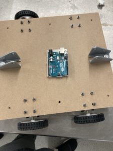
I was able to successfully drive the motors from the FPGA, a significant milestone for the physical control aspect of our balancing platform. Additionally, I obtained some decently accurate readings from the IMU. While initially attempting to implement sensor fusion algorithms, I discovered the gyroscope data appeared incorrect, causing fusion results to be unreliable. As a result, I pivoted to using direct calculations instead of sensor fusion methods. To address the gyroscope accuracy issues, a new IMU has been ordered to determine if we can get more accurate gyroscope data for potential future integration of sensor fusion algorithms.
The project is slightly behind schedule as I haven’t yet finished setting up the complete serial communication for system debugging. To catch up with the project timeline, I plan to finalize the serial connection setup, implement additional testing procedures, and optimize the current SPI configuration to ensure reliable data transmission.
By tomorrow (Sunday), since mid-demo is on Monday, my primary goal is to get the IMU fully integrated with the motors such that the motors are driven based on the IMU data. This integration is critical for demonstrating the core functionality of our balancing platform. I’ll focus on implementing the control loop that reads orientation data from the IMU and converts it into appropriate motor control signals to maintain balance based on the detected platform angles. In the latter half of the week, I plan on beginning testing to tweak anything on the software side to make sure that our robot functions as desired.