Team Status Report for 2/22/2025

One of the biggest risks we face is the weight of the pistons. They are heavier than expected, which may affect the robot’s structural integrity. To address this, we plan to use a combination of smaller and larger pistons to lift the platform without compromising stability. If this approach is not feasible, we have two contingency plans. The first option is to use two boards instead of one to support the piston mounts. The second option is to reduce the number of pistons on the platforms to decrease overall weight. These solutions will help maintain the structural integrity of the robot while ensuring the pistons function as intended.

Another risk is the delayed delivery of parts. To mitigate this, we are working with the components we currently have and actively following up on pending deliveries to keep progress on track. While waiting for critical components, we prioritized tasks that could be completed with available materials to minimize downtime. This approach will help prevent significant disruptions to the overall project timeline.

A minor design change was made to improve stability. Initially, the robot was designed with four columns, but we increased it to six to better support the boards, pistons, and platform. This adjustment ensures the structure is strong enough to handle the load and reduces the risk of mechanical failure. However, this change also introduces a challenge: reduced space between the first and second board, which may make it more difficult to access and repair electronic components like the FPGA. As a result, we may need to disassemble parts of the robot when making adjustments. While this adds complexity to maintenance, the improvement in structural integrity outweighs the drawbacks.

Due to delays in part deliveries, we have pushed back the completion of the full design of the wheelbase, as the wheels have not yet arrived. Similarly, the FPGA system has been delayed since some components are still pending. To maintain progress, we are focusing on assembling and testing available parts while waiting for the remaining components. When the delayed parts arrive, we will focus on integrating them promptly to get the project back on schedule.

Sara’s Weekly Update 2/22/2025

This week, I completed the base for the project. I cut the board into an 11” x 12” square and drilled the necessary holes for the column (M5) and the motor mounts. However, I only attached one motor mount instead of fully assembling the board. This decision was made to ensure enough space in our red box and to allow me to map out the electronics before the final assembly. I wanted to avoid repeatedly disassembling and reassembling the base and columns before integrating the electronics.

A significant step forward this week was the arrival of our battery boards and motors. I drilled six holes for the mount, but during this process, I noticed that pushing while drilling caused the wood around one hole to break, making it unstable. As a result, I had to cut and drill another board. Despite this setback, I am back on schedule.

IMG. 1: Cut Board (12″)

IMG. 2: Cut Board (11″)

I am slightly behind due to the delay in the arrival of the wheels, which are needed for fitting. However, aside from that, I am satisfied with my progress. Once the wheels arrive, I am confident that I can fully construct the base. To make up for this time, I plan to focus on completing the rest of the robot build and installing the pistons.

Next week, I plan to install the FPGA and other electronics onto the board, finalize the piston on the second platform, and complete the platforms holding the water.

Sara’s Weekly Update 2/15/2025

This week, I updated the Gantt chart to reflect our new goals for building progress. I ordered parts for the robot base, including boards, wheels, nuts, and washers. I also revised the platform design. Initially, we planned a metal frame, but we’re switching to a board-based design with motorized wheels. Wood is easier to drill into to make space for columns and mounts. If water spills, we can wipe it off.

WheelBase and Motorized Wheel

IMG. 1: Wheelbase and Motorized Wheel

I’m somewhat disappointed with our progress, as I spent too much time refining the design instead of moving forward with physical implementation. I appreciate Hyong for helping me break that habit. To catch up, I aim to complete the wheelbase with columns.

Next week, we have presentations for the design proposal, so I’ll focus on preparing the slides. Additionally, I plan to help with the base by cutting it to size (12” x 12”), drilling holes for the columns and motor mounts, and attaching the mounts.

PART A:

The slope-stabilizing robot improves public health, safety, and welfare by handling deliveries on sloped surfaces. Automating this process reduces strain on workers and lowers the risk of injuries. The FPGA ensures real-time stability, preventing spills. For hazardous chemicals, the robot minimizes human exposure and reduces long-term health risks. Its stability also prevents agitation, making chemicals safer and easier to handle.

PART B:

Socially, the robot boosts efficiency and safety by simplifying difficult deliveries. Restaurants, cafes, and event spaces can reduce labor-intensive tasks, allowing workers to focus on service. In industries handling chemicals, its stability ensures smooth uphill transport for safer handling, making it valuable for laboratories, manufacturing facilities, and medical environments.

Team Report for 2/15/2025

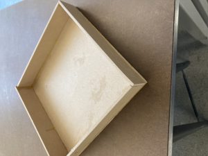
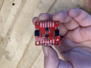
We purchased new parts for the robot (IMUs, wheels, boards, motors, nuts, washers, and M5 threaded rods) and a storage box for organization. We focused on implementation and building and acquired an FPGA to enhance functionality.

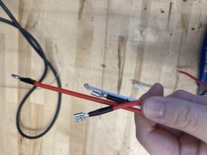
One of the most significant risks is the robot’s ability to handle 45º and 60º inclines while maintaining stability. To address this, we are refining our design and testing different configurations. Another major risk is the exposure of electronic components (FPGA, IMUs, etc.) to water during testing. To mitigate this, we are using an extra board on top of the electronics as an extra shield. These were brought up in the project proposal and we decided to address these immediately.

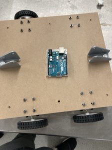
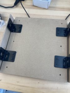
We modified the wheelbase design to better protect the electronics and simplify construction. Rather than a plexiglass shield, we added another wooden board with threaded columns to hold everything together.

Due to our focus on research and planning, our plans were slightly delayed. As a result, we are prioritizing the integration of our current components into the wheelbase to get back on track. Next week, we will assemble the base, begin working with the FPGA, finalize the design proposal before Sunday night, and prepare for its presentation. Moving forward, we will continue refining our design while ensuring that testing and implementation remain on schedule.

As for the extra questions for this week’s status reports, A and B were written by Sara while Raymond wrote C.

PART A:

The slope-stabilizing robot improves public health, safety, and welfare by handling deliveries on sloped surfaces. Automating this process reduces strain on workers and lowers the risk of injuries. The FPGA ensures real-time stability, preventing spills. For hazardous chemicals, the robot minimizes human exposure and reduces long-term health risks. Its stability also prevents agitation, making chemicals safer and easier to handle.

PART B:

Socially, the robot boosts efficiency and safety by simplifying difficult deliveries. Restaurants, cafes, and event spaces can reduce labor-intensive tasks, allowing workers to focus on service. In industries handling chemicals, its stability ensures smooth uphill transport for safer handling, making it valuable for laboratories, manufacturing facilities, and medical environments.

PART C:

For economic considerations, although many robots are supposed to replace humans and help keep business costs down, our robot is meant to aid humans without replacing them. This robot has capabilities specifically for when dangerous chemicals can not be disturbed and shaken. For production, instead of an FPGA, it would make more sense to purchase a microcontroller as the cost of an FPGA does not offset the hardware acceleration that it provides. We are also using wood in our design because it is easy to work with, but for production, it would make more sense to use a material that is waterproof and lightweight such as plastics. This robot is designed to be small and only has a few parts, so distribution should be relatively simple compared to other more complex robotics products.

Sara’s Post for 2/8/2025

This week, I focused on designing a wheelbase and its motor. I mainly did this after feedback from the project proposal mentioned that it would take more power to go up a 60-degree slope. This week, I considered two setups: two motors per side or one or one motor connected to wheels. The two-motor setup is way more powerful, but I still need to refine it. One motor per side needs more mechanical work and has less power, so I’m leaning toward two.

Another feedback was on how the robot’s FPGA and circuits are protected from water from our testing glasses. To protect our components, I am thinking about using a flexi-glass cover. I worked with one  Since we are working with water, we might consider components that are easy to wipe off to prevent mold from growing. Or we take extra precautions to make sure we wipe down components. We are thinking about raised edges and magic for the platform to show the water does not slide. The raised edge has to be watertight to prevent the leakage on the board.

I also put in a purchase request for a motor and motor driver, which got approved. I researched brushless motors because, as I mentioned earlier, I was worried about our robot’s ability to climb a slope. I chose 775 DC Motor 12v DC Motor High Torque DC Motor Max 20000 RPM Dual Ball Bearings Quiet Power Wheels Motor Upgrade DC Motor (this is the listing name on Amazon) because it was at a great rpm and was utilized in driveable children’s toy cars, which made me confident this could reasonably drive our robot. I researched the motor driver and I was happy that it was compatible with both the FPGA and the motor I wanted to use, and its use in electric skateboards.

This week, I focused on working on the project presentation as I was presenting. Raymond and I made sure we had the right number of slides, justification for our choices, and making sure the slides looked nice and neat.

Right now, I feel good about where I’m at. I’ve got the wheelbase design down and worked through some problems that came up during the presentation. The next big task is figuring out the lifting mechanism and finalizing a robot design. On Sunday, the design proposal is due, which is huge goal.