Team Weekly Update (4-26-2025)

A major issue has been with the IMU, which has been giving faulty results. This causes the linear actuator (LA) to rapidly adjust or over-adjust. Initially, we thought the errors were caused by vibrations. So we tested by tilting the robot forward and backward to see how the IMU responded. While this helped somewhat, there were occasional faulty data points when tilting. The IMU responded inconsistently, leading to unstable platform behavior. To address this, we have been testing the IMU in different scenarios and have added foam around it to reduce vibrations. Additionally, we moved the IMU to the center of the platform to get more stable readings and changed the start time of data collection to help with initialization issues. Another problem is that the wheels sometimes came off during testing. To solve this, we plan to superglue the wheels onto the axles.

Regarding design changes, so far we have made only small adjustments. The most notable changes are relocating the IMU to the center of the robot for better stability and deciding to use only one battery instead of two.

Because of some IMU challenges, we are slightly behind schedule on FPGA integration.

For unit testing, we first tested the IMU on flat surfaces and tilted the robot to verify that the data was recorded correctly. We also created a program that allowed us to input text commands to control PWM and direction, and verified the outputs using an oscilloscope.

For overall system testing, we drove the robot up a measured ramp. Then the imu’s data (angle, speed, etc) was recorded. A video was also taken. If we were testing with water, we used a water bottle to prevent spilling and watched the video to see if the water was over a certain threshold. We tested the robot both with and without water to study how the load affected performance. Through experimentation, we found that we could only fill the container to about 70% full without significant water spillage, unless we very carefully placed the robot so that the front wheels made contact with the ramp first. This minimized water sloshing at the start. Other testing discovered that our robot tended to curve to the left, which led us to realize that some of our wheels were not aligned properly. After repositioning and securing, the robot drove much straighter.


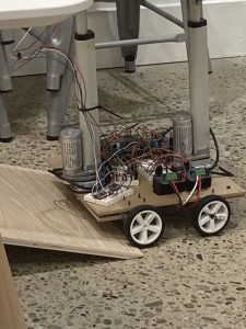
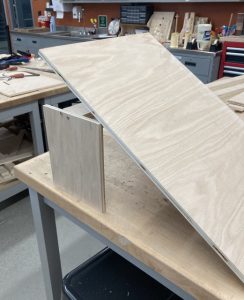
IMG 1: The New Robot Positioning

Below are several videos showing our testing process. Some early tests show issues like poor traction, unstable IMU readings that caused the LAs to “shake”, and minor bugs in the code.

Poor Traction: https://drive.google.com/file/d/1WCRZMwPiRRYIEO_k6S9NhSe–4uCuD7E/view?usp=drive_link

IMU: https://drive.google.com/file/d/1WiQ-6zIasJhYvzdJRrbxLwdb7-xIRUrI/view?usp=drive_link

Minor Bugs: 1 & 2

The results from our successful runs: Water & Without Water.

Sara Weekly Post (4-26-2025)

This week, I presented our final presentation. I began working on the final poster and report. We focused heavily on testing our robot. I filmed the robot climbing up the ramp and tested it on the ground to see how our wheels were performing. I found that the wheels were uneven, causing the robot to drive in multiple directions. To fix this, I removed the wheels and meticulously repositioned them until they rolled straight. I also tried to glue the remaining wheels to prevent them from falling off during testing, however, I might try and use super glue instead of hot glue later.

For testing, we built a ramp, and every time the robot went up, I moved it back to its starting position. During some of the tests, I discovered we didn’t need to implement our system with two batteries.

This week, we are on schedule with our robot, and we continue to test it regularly. We also have spare parts ready in case anything breaks.

Next week, we will test the robot to get it into its best condition. We plan to finish all final class documentation (poster, video, and final report) and prepare for a great demonstration. I might also superglue the wheels to the axis to keep them straight.

Sara’s Weekly Report (4-19-2025)

This week I wired up the IMU on the top shelf and helped with testing. We had an issue with a bump on the ramp. I tried sanding and using several methods to fix it. Eventually, a TechSpark employee used a table saw to cut off the edge, and then we smoothed it out with a sander.

During this time, I also wrote some code for the Arduino to control one of the linear actuators. I worked on our final slides, set up testing parameters, and listed what we need to measure. I also made a color-coded guide for our wires in case we forget their purpose.

I think I am on track this week because most of our tasks are finished.

Next week we have a lot of preparation to do for presentations, final demos, posters, and reports. We also need to finish the final touches on the robot. I will be presenting our final presentation, so I plan to practice what I want to say about our project. We also have some testing to gather more data for the presentation and report.

While working on this project, I learned about FPGAs and IMUs through our sensing system. The most important lessons I learned were about time management and wire organization. These have always been hard for me in the past. Setting goals and creating a clear schedule helped. When things went wrong, we were able to handle them because we had planned. One part that took much longer than expected was dealing with tangled wires. Having a good system for organizing them made things much easier.

I learned the most through trying and failing. It cost us a bit, but we learned a lot each time. We replaced parts, tried new approaches, and made improvements based on what we saw. Online forums were also helpful because they are full of shared knowledge. Our problems were sometimes very specific, so it was great to find people who had gone through similar things. Short videos helped too because they get straight to the point. I watched one about capacitors that helped me think more about voltage and current when testing motors. These tools helped me think in new ways and pay more attention to the little details.

Team Weekly Update (4-19-2025)

Our biggest problem is that, for some reason, the motor drivers and the Arduinos are receiving excess voltage. We do not know how this is happening. However, this has caused us to burn through (not literally) several motor drivers and at least two Arduinos. We are managing this issue by constantly checking the Arduinos and motor controllers. We have backups and meticulously test the wires to ensure they are safe.

Another issue is that our robot tends to drive off the ramp on its left side. This is caused by the board bending and the robot being too wide. We plan to drill out the wheels to create a narrower wheelbase.

We did not make any significant changes to the robot itself, but we did modify our ramp. We shaved down the edge to allow for smoother robot climbing. We also changed our specifications because we had difficulty reaching a 45-degree incline.

There are no schedule changes.

Video: Wonky Drive,

Video: Test Drive

Video: Test Drive with Two Cups

Team Update – April 12, 2025

This week, the most significant risks identified include the bending of the board and the possibility of wires coming loose. The board bending is particularly concerning because if it bends too far, it could snap and damage critical components. Additionally, we’ve been having trouble keeping the wires securely connected, which can interfere with power and signal delivery. To address the bending issue, we’ve added an extra board underneath to help stabilize the structure. If this solution proves insufficient, we plan to glue the board for extra support. To prevent wires from disconnecting, we’re being more gentle during handling and may consider better cable routing or retention methods going forward. We also might use superglue to attach the wires to the board.

For design changes, we are adding the IMU and its circuit inside the platform. This placement will allow us to better monitor changes in movement or orientation on the platform.. However, this update also introduces the need to waterproof the circuit. Additionally, we’ll need to design and install wires long enough to connect the IMU from the platform to the main board below. These are relatively small changes.

There is a change where we might measure and record our results and simultaneously improve our robot.

Video of our platform working: https://drive.google.com/file/d/1AWDLh1zZTwN2v7Hf4jVGB7jIczxpfVpt/view?usp=sharing

Sara’s Weekly Update – April 12, 2025

This week, I helped wire and connect our new motors to the board, along with the linear actuators. I was pretty excited because we received a bunch of new parts for the robot. I also built a new wheelbase since we had to purchase new mounts for both the linear actuators and motor mounts, which required drilling a new board.

I made new wires for the motors and moved all the electronics onto the new board.

We also got a new room to store our robot, which allowed us to attach the platform. Unfortunately, I initially purchased the wrong level shifters, the wrong item, and the wrong shaft size. However, I improvised attachments using yarn and tape. I also reversed the wheel so the shaft rested on the outer rim. Later, I got the correct shafts, but they were too long and were bending the board, so I had to carve them down.

To address the bending issue caused by the board’s weight, I added an extra support board and secured it using leftover M5 screws as a temporary fix.

At one point, I accidentally burned out the Arduino, but I replaced it with a new one. I also finished purchasing the ramp.

I rewired the entire board, separating the linear actuators (LAs) and the motors onto separate boards because the signal interference was causing issues. I also rewired the LPWM and RPWM to always be enabled, which improved the control and correction.

Although we’re currently a bit behind schedule due to delayed parts, I plan to catch up by continuing to assist Raymond and keeping track of the robot’s measurements and performance.

Next week, I plan to start on the slides for the final presentation and meticulously run the robot for results.

Sara’s Weekly Update-March 29, 2025

This week, I focused on getting the IMU working to process inputs and outputs. While I didn’t make much progress on the IMU itself, I contributed significantly to motor testing. I realized that we needed a lower RPM for higher torque, which led to switching to motors with a lower RPM. Initially, I attempted to decrease the RPM using a resistor, but this prevented the motor from functioning properly. Later, I tried using a capacitor to supply additional current and power, but during testing, I accidentally sent a wheel flying across the lab. I’m sorry. Through these experiments, we discovered that connecting multiple motors leads to a voltage drop, which I plan to fix by adding capacitors in parallel.

IMG. 1 – OLD RAMP

IMG. 2 – NEW RAMP

In addition to motor testing, I worked on the linear actuators (LA), testing them with an Arduino as we encountered issues with the code used to control them. Another key task I undertook was building a ramp for testing. Initially, I designed a standard adjustable ramp similar to a folding chair mechanism. This took about three hours to construct, during which I used M5 rods to lower the height and adjust the angle. After consulting an expert, I revised the design and switched to using two M5 threaded rods for better adjustability.

I am behind on this project with little time left, so I plan to dedicate significant time to working on the circuit, catching up, and putting in extra hours.

My main goal is to get the robot running and begin testing as soon as possible. I also hope to finish the ramp to test inclined angles and assess balance with water on top.

Sara’s Weekly Update (March 22, 2025)

We are caught up with the physical build. The robot is currently designed for testing: a detachable platform to test for slop climbing, and a small linear actuator (LA) for platform testing. I drilled the L brackets onto the platform and the LA onto the board. I also completed the rest of the motor controllers to motor wires.

IMG 1. Completed Board and Platform

IMG 2. Completed Wheelbase with mounted LA

IMG 3. Added Mounts to platforms

I got our LA to run. Here is a link to the video. https://drive.google.com/drive/folders/1XDY6sC3153WC3wEnl2y9C_0TSnG_CBZb. During this part, I fried a motor controller… Sorry.

I tried to use yarn to stabilize our LA, did not work. We purchased a P-series mount to straighten the LA’s when the bot is going up a slope.

I am on schedule with the robot body, as we previously discussed that testing would be conducted in a different manner to accommodate a testing schedule for individual parts. I decided not to install the electronics yet since they are needed for separate component testing. To compensate, I plan to fully utilize this testing mode to make sure our robot works completely. This involved drilling holes in the platform for the mount, which could result in water leakage onto the board.  I plan to glue pieces of wood to the platform and the bottom for added security when we add the different p-series.

However, we are behind schedule on the robot itself. While we have the code, we are rushing to complete implementing it. To compensate, we plan on working on smaller parts and combining them later.

Next week, I plan to assist Raymond with his work and continue testing the robot platform and its driving capabilities.

Team Update (March 29, 2024)

The most significant risk to this project is the power and the FPGA and IMu not communicating with the robot. We are having issues with plugging in multiple motors, which is causing the voltage to drop across all devices. This means we cannot continuously drive the robot on the slope. We are also having issues with imu outputting accurate data. We have managed this issue by using capacitors to increase the voltage, and we planned for this by using two batteries. We might want to get a battery with the same voltage but with a higher amperage output. For the imu, we are rewriting the algorithm to account for the calibrations. We want to get a better IMU for more accurate calibration.

At this point, there are some changes to the electronics as different motors have been purchased with a lower rpm to get a higher torque. This is needed to get the robot driving. We also might have to add some capacitors to the electronic design for more voltage, since there is voltage dropping and we constant voltage across all the motors. This has cost some money, but this is a completely easy fix when we get the motors.

Our schedule this week has primarily focused on testing the robot. The updated plan prioritizes testing the robot and its performance. Moving forward, our next steps include implementing these fixes, testing the robot under real-world conditions, and refining the overall system to ensure reliability and functionality.