Raymond’s Status Report 4/19/25

This week, I’ve put the whole system together with the Arduino. On Sunday, I ran into some connectivity issues with the FPGA and the IMU, but had successfully gotten all the motors running simultaneously with the new logic level shifters. The connectivity issues with the IMU seemed to stem from unstable wire connections, as it would connect and run for a bit, but then lose the connection and not be able to communicate with the device. When running a program just to read from the IMU, it runs well. But when running a program to activate the linear actuators, while reading from the IMU; it loses connection.

After Sunday, we decided to get the whole system running with the Arduino. I created a few different programs just to test the functionality of the motors, all connected together. First, to test whether all of the motors ran, I ran a script where I could run the wheels forwards/backwards, and the linear actuators up/down. I ran into some issues with this because there were some issues with the motor drivers again. But after we diagnosed the issues and replaced some of the motor drivers, we went to drive the linear actuators based on the angle of the IMU. Then I created a short run that would stop after two seconds of the robot trying to climb up the ramp. The runs were not very good because the ramp had a large lip, and I needed to run the robot pretty quickly, so the linear actuators had trouble adjusting in time. As Sara was able to smooth out the lip, I was able to run a program that incremented the duty cycle of the motors until it could get over the lip. This ensured that the robot used a minimal speed to get over the ramp, so this gave the linear actuators the best chance to adjust in time.

https://drive.google.com/file/d/1VAoIBAHETLK4q6Kjd93y6QgunjlTJPVh/view?usp=drive_link

Our schedule is behind. We want to conduct some more testing on different angles and actually get some water in the cup so that we can know how much angle we can accomodate before spilling the water. If the professor feels that this progress is good enough, I also want to replace the Arduino with the FPGA. Once I am able to debug why the IMU and FPGA have connectivity issues for certain programs, it will be at similar progress as the Arduino.

The deliverables for the next week are to test on higher angles. I think it would be beneficial to slow the robot down more, after the first set of wheels get over the lip. Then once the back wheels struggle to get over the lip again, we would continue to increment the duty cycle. This would give the linear actuators the most time to adjust its angle. Also swapping from Arduino to FPGA would also be a deliverable for the next week. 

Questions for the week:

As you’ve designed, implemented and debugged your project, what new tools or new knowledge did you find it necessary to learn to be able to accomplish these tasks? What learning strategies did you use to acquire this new knowledge?

As I was learning how to use the FPGA for the project, I read a lot of different projects on Hackster for how to drive wheels with an FPGA. I also read a few different article on how to use SPI and I2C with the FPGA on Hackster. My learning stategies were just to read different ways to solve the problem so that I had a better understanding, so that I could apply the concepts to our own project. Working through the project, I also did some circuit debugging that I haven’t done since 18-100. I think it was beneficial to go through the steps to diagnose problems and isolate potential issues. Reading the documentation to know that certain voltage levels don’t work and Googling how to solve those issues was another strategy. Watching Youtube videos on FPGA projects that did similar things, also aided in the project. The Arduino portion of the project, I just worked through it as the documentation is very clear and the integration is seamless.

Raymond’s Status Report 4/12/25

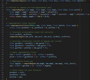
Over the last two weeks, I’ve been working on getting the whole system working together. For mid-review, we were able to get the linear actuators moving such that when we tilted the platform, the IMU was able to detect that once the board was no longer at 0 degrees from the ground, the linear actuators would activate to even out the board. That IMU that we were using ended up breaking, and we knew this because it would get very hot to the touch when just supplying the correct input voltage. We purchased a new IMU, the BNO085, but when trying to read the data with I2C, I realized that it uses Sensor Hub Transport Protocol (SHTP), which is different from the standard I2C. So, when I was trying to access the different registers to get the sensor data, it would not return the correct information. This resulted in having to buy another IMU, the MPU 6050. I decided against buying the original IMU that I was working with because the gyroscope data was oddly inaccurate, and I had previously worked with the MPU 6050. Once the MPU 6050 arrived, through the PYNQ framework, I was able to receive the IMU sensor data and apply a simple complementary filter to get pretty accurate orientation readings.

In order to get the motors running with the PWM signal from the FPGA, I needed to use a logic level shifter since the PWM signal from the FPGA is 1.8V. I was able to successfully get all four wheels running, but just by moving the wires around, it would change behavior of the motors. They would either stop running, or they wouldn’t stop running when they were supposed to. After doing some research, I realize that this is probably because of capacitance coupling that is amplified by the level shifter. Our wires being longer does not help with this behavior, so I got a new level shifter that is supposed to be more resistant. In the meantime, we will be continuing with Arduino, such that we can test our control algorithm.

Throughout the last two weeks, we also decided to just try and get the system running with an Arduino since we were running into some blockers with the FPGA, so while simultaneously trying things with the FPGA, I was working on getting the system working with the Arduino. This was pretty simple since there is a lot of technical support for Arduino.

We are behind schedule, but we are moving along and not letting the blockers get in the way. We are working on tasks with the Arduino that can be replicated on the FPGA, so that we do not fall too far behind while working with the FPGA.

By Monday, I plan to have the whole system running up a ramp for two feet, while adjusting its platform. I will need to change the setup for the Arduino system such that are linear actuators extend halfway at the very start. Then, to make any adjustments, both linear actuators will run, but in opposite directions, so that we can increase the speed at which we change the angle of our platform. Then I will continue working on the control algorithm such that it reacts immediately to any change in slope, and try to reduce any oscillations.

Raymond’s Status Report 3/29/25

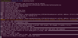
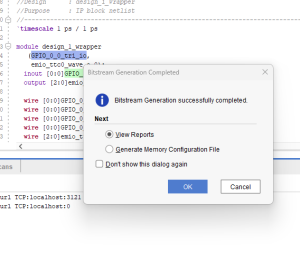
This week I focused on establishing the hardware and software foundation for our two-piston balancing platform. I created a Vivado block design for the Ultra96 board with SPI interface configuration, successfully implementing the design and generating the necessary files for PetaLinux integration to prepare for the software development phase.

On the software side, I built a custom PetaLinux image with SPI drivers enabled, modified the device tree to properly configure the SPI interface, and created the necessary boot files for the Ultra96 board. For communication testing, I established a serial connection for debugging the system boot and verified the initial boot sequence, which confirmed that the basic hardware configuration is working as expected.

I was able to successfully drive the motors from the FPGA, a significant milestone for the physical control aspect of our balancing platform. Additionally, I obtained some decently accurate readings from the IMU. While initially attempting to implement sensor fusion algorithms, I discovered the gyroscope data appeared incorrect, causing fusion results to be unreliable. As a result, I pivoted to using direct calculations instead of sensor fusion methods. To address the gyroscope accuracy issues, a new IMU has been ordered to determine if we can get more accurate gyroscope data for potential future integration of sensor fusion algorithms.

The project is slightly behind schedule as I haven’t yet finished setting up the complete serial communication for system debugging. To catch up with the project timeline, I plan to finalize the serial connection setup, implement additional testing procedures, and optimize the current SPI configuration to ensure reliable data transmission.


By tomorrow (Sunday), since mid-demo is on Monday, my primary goal is to get the IMU fully integrated with the motors such that the motors are driven based on the IMU data. This integration is critical for demonstrating the core functionality of our balancing platform. I’ll focus on implementing the control loop that reads orientation data from the IMU and converts it into appropriate motor control signals to maintain balance based on the detected platform angles. In the latter half of the week, I plan on beginning testing to tweak anything on the software side to make sure that our robot functions as desired.

Raymond’s Status Report 3/22/25

This week, I made progress on implementing the motor control system using the Ultra96 FPGA development board. My primary focus was on configuring the Timer Counter peripheral to generate precise PWM signals for variable speed control of our DC motors. After examining the board documentation, I determined the appropriate pin mappings for routing the timer outputs to the external connectors where our motor driver circuitry will interface.

I spent considerable time analyzing the C application code that implements an interactive console interface for selecting different motor speeds. The code efficiently configures the timer hardware, sets up interrupt handlers, and implements PWM generation using the match mode functionality, which allows for precise duty cycle control without requiring constant CPU attention.

During testing, I encountered some unexpected challenges with the development environment. I discovered that our board was running a Linux image that prevents direct hardware programming, and that the Ultra96 requires a specialized adapter for complete debugging capabilities. While these issues have slightly delayed the implementation timeline, I’ve identified clear solutions. For the coming week, I plan to either acquire the necessary adapter or create a custom boot configuration, complete the hardware setup, program the FPGA with our control logic, and begin physical testing with the motor driver to validate the speed control functionality across different duty cycle settings.

Team Status Report for 3/15/25

The biggest risk factor is the robot being unable to move or the platform not working by the end of this week. Some things that may contribute to this problem are if the custom IP block for the IMU does not end up being useful. As a contingency plan, we may send the IMU data from the Arduino through UART, which should make retrieving and using the IMU data easier. Another concern is the speed at which our linear actuators move. The fastest rate for change in angle will be when the robot is driving from a flat surface onto a ramped surface, so we plan to slow the robot down if the linear actuators are unable to adjust quickly enough. Before, our systems for the wheelbase and the platform were independent, but we think that we could have the two systems interact to solve this issue. Another risk is keeping the pistons still. To address this, we plan on wrapping the axis with yarn to keep it still. As a contiguency, we might hot glue the yarn for more security.

We made the changes to attach the electronics using velcro tape instead of screwing them onto the base. This was done to save time on reattaching/attaching the electronics on the board. The cost is $9.51.

There is a huge schedule change. We plan on getting the robot moving, the platform tilting, and the bot moving by the end of next week so that we can test and tweak the system. We expect to run into many issues, so we made this change.

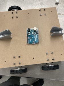
Completed the Wheelbase with Arduino

Raymond’s Status Report for 3/15/25

This week, I was working on getting the motors to react to the IMU sensor data. I first tried to access the sensor data using the PYNQ framework. I was able to successfully access the device, but was unsuccessful in retrieving any useful data from the IMU.

i2c addresses present on i2c-3 (top) and i2c-2 (bottom)

Read / write and read over I2C to verify the write

Compared to Arduino, where you can easily extract the IMU data by calling some methods, I have not found a solution for the FPGA yet. I have also looked into a few different projects on Hackster, working with FPGAs and driving motors. Our FPGA is a Zynq Ultrascale+ MPSoc, while the projects on Hackster drive their motors with a Zynq 7000 SoC device, so mapping the block diagrams has been a bit difficult. Also, I found another project that sends IMU data from an Arduino through UART, but for the Ultra96, it would need an additional UART module, so I’ve been a bit hesitant. So throughout the week, I’ve been trying to map the Zynq 7000 module to the Ultrascale+ module, to get the motor driven. I’ve also looked into designing a custom IP block for the IMU since there’s a similar project controlling the motor with an ultrasonic sensor that is typically used for Arduino and they had built a custom IP block.

Based on our weekly meeting, and our own expectations, I have fallen behind in getting the FPGA integration done. But, if we are able to get the motors reacting to the IMU data by the next week, and get a preliminary system built, we are expected to be back on track.

In the next week, I plan to design a custom IP block for the IMU to get the data to be used for driving the motor. By the end of the week, I plan to be able to drive the motors based off the IMU data.

Raymond’s Status Report 3/8/25

This week the goal was to get the FPGA programmed to be able to receive the sensor data from the IMU as well as be able to output a signal such that the motors are driven. I was working with the PYNQ environment and had some trouble getting the environment set up. Eventually, though, I was able to get the PYNQ environment working, but I still had problems getting the sensor data. There is nothing showing up in the place where I expect the data to be. I wasn’t able to debug it for too long because I left for spring break early.

The progress is behind because our team wanted to get the goals of reading the IMU data and outputting a PWM signal to the motors done, but we were unable to get it done successfully. I plan on getting the IMU sensor data receiving working by Wednesday, by trying to debug the system. I also plan to get the motor output done by Wednesday. By the end of the week, I can work on incorporating the IMU sensor fusion algorithm in Vitis so that the raw IMU data can be seen as positional/angular data, which will be useful for us.


Part B:

With cultural factors, because we are automating hazardous materials transport, there are the considerations in law for who will be responsible if a device such as our Slope Stabilizer Robot were to injure someone. We want it so that robots can be used to aid humans to reduce the risk of injuries, but we also don’t want to take away from human jobs. Our simple user interface makes it accessible across language barriers and varying technical expertise levels, allowing for diverse workplace environments.


Part C:

From an environmental perspective, the Slope Stabilizer Robot offers significant benefits by substantially reducing the risk of chemical spills that could contaminate the environment such as soil or water. The current prototype uses wooden components, a renewable resource with lower carbon footprint than plastics,  and future iterations could incorporate more sustainable materials and energy-efficient systems.

Raymond’s Status Report for 2/22/25

This week, I started implementing some code on the FPGA, specifically the complementary filter for the IMU data. I looked into the different kinds of filters such as complementary, Kalman, and Madgwick filters. Ultimately I decided on the complementary filter because it is the simplest to implement. However, if the accuracy of the data is not good enough, I may move to a Kalman filter because I could use the FPGA hardware to do the necessary matrix computations. I also watched a few videos on using FPGA’s for embedded systems projects which gave me a good idea for integrating all the sensors with the FPGA.

The schedule is a little behind once again because the IMUs have not arrived yet. So, I wasn’t able to test if the FPGA can receive data from the IO pins. Once the sensors come in, I expect that I will be able to quickly test the IO ports and get the sensors integrated with the filtering algorithm.

In the next week, I hope to get the sensors integrated with the system. The motors have also arrived and the motor drivers were ordered recently, so if the motors arrive, I also expect that I can test the FPGA with the motors.

Raymond’s Status Report for 2/15/25

This week, I was working with Sara to figure out the entire design of our stabilizing robot. The part specifically that I was working on this week was the interfaces for the FPGA to be able to access IMU data as well as output PWM signals to the motors. I began the setup process of the FPGA, but have yet to figure out the software implementation completely. I am researching the pros and cons of using either PYNQ (Python) or Vitis (C/C++) for the software to read the IMU data. I want to use the FPGA logic elements for generating the motor outputs, however, so I am leaning toward Vitis. I have also been working with Sara to complete the Design presentation, and have been preparing for the presentation I will need to do.

Our progress is a little behind. We planned to be able to begin testing as soon as possible, but we are currently waiting for parts to arrive. So we are going to get the whole system ready such that when the right parts arrive, we already have a base that we can test the system with, instead of starting the logic designing step once the parts arrive.

Throughout the next week, after completing the presentation, I want to set up some logic on the FPGA, such that once the motors and sensors arrive, I can quickly integrate them into our system. I would like to perform the IMU sensor fusion algorithm on the FPGA, so I could start by writing a module and creating a testbench as well.


Team Status Report for 2/8/25

The most significant risks that could jeopardize the success of the project are that if the parts we ordered are not able to complete the capabilities that we expect them to do. We did research into the parts that we have ordered already to ensure that they are compatible and have the basic capabilities, but you never know how well they will work until you actually begin to test them. Another point that could jeopardize the project would be if the IMUs are not precise enough. Since the basis of our project is that we need to balance cups of water precisely so that there is no spillage, we will need the IMUs to be able to provide accurate data so that we can smoothly adjust our platform to balance the cups of water.  We will manage these risks by starting early and testing early. If we figure out that some parts that we planned on using are not good enough for our project, we will continue to do research and find the parts that can do what we need. We are confident that this robot is achievable within the budget since there are many examples of robots using IMUs to perform balancing tasks online, so it will just come to figuring out the correct implementation.

As we move from the proposal stage to the design stage. we are still designing our system, so there will be many changes throughout the next week, such as what kind of platform we will use and how we will prevent water from spilling and affecting the electronics. Generally, our requirements have remained the same, but as we continue to design our system, we will be zooming into the finer details and making changes there. The costs of the small detail changes should be within the total budget and are not expected to change the cost of the device or affect the requirements.