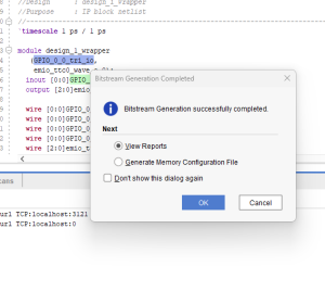
This week, I made progress on implementing the motor control system using the Ultra96 FPGA development board. My primary focus was on configuring the Timer Counter peripheral to generate precise PWM signals for variable speed control of our DC motors. After examining the board documentation, I determined the appropriate pin mappings for routing the timer outputs to the external connectors where our motor driver circuitry will interface.
I spent considerable time analyzing the C application code that implements an interactive console interface for selecting different motor speeds. The code efficiently configures the timer hardware, sets up interrupt handlers, and implements PWM generation using the match mode functionality, which allows for precise duty cycle control without requiring constant CPU attention.
During testing, I encountered some unexpected challenges with the development environment. I discovered that our board was running a Linux image that prevents direct hardware programming, and that the Ultra96 requires a specialized adapter for complete debugging capabilities. While these issues have slightly delayed the implementation timeline, I’ve identified clear solutions. For the coming week, I plan to either acquire the necessary adapter or create a custom boot configuration, complete the hardware setup, program the FPGA with our control logic, and begin physical testing with the motor driver to validate the speed control functionality across different duty cycle settings.

