Raymond’s Status Report 3/29/25
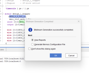
This week I focused on establishing the hardware and software foundation for our two-piston balancing platform. I created a Vivado block design for the Ultra96 board with SPI interface configuration, successfully implementing the design and generating the necessary files for PetaLinux integration to prepare for the software development phase.
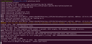
On the software side, I built a custom PetaLinux image with SPI drivers enabled, modified the device tree to properly configure the SPI interface, and created the necessary boot files for the Ultra96 board. For communication testing, I established a serial connection for debugging the system boot and verified the initial boot sequence, which confirmed that the basic hardware configuration is working as expected.
I was able to successfully drive the motors from the FPGA, a significant milestone for the physical control aspect of our balancing platform. Additionally, I obtained some decently accurate readings from the IMU. While initially attempting to implement sensor fusion algorithms, I discovered the gyroscope data appeared incorrect, causing fusion results to be unreliable. As a result, I pivoted to using direct calculations instead of sensor fusion methods. To address the gyroscope accuracy issues, a new IMU has been ordered to determine if we can get more accurate gyroscope data for potential future integration of sensor fusion algorithms.
The project is slightly behind schedule as I haven’t yet finished setting up the complete serial communication for system debugging. To catch up with the project timeline, I plan to finalize the serial connection setup, implement additional testing procedures, and optimize the current SPI configuration to ensure reliable data transmission.
By tomorrow (Sunday), since mid-demo is on Monday, my primary goal is to get the IMU fully integrated with the motors such that the motors are driven based on the IMU data. This integration is critical for demonstrating the core functionality of our balancing platform. I’ll focus on implementing the control loop that reads orientation data from the IMU and converts it into appropriate motor control signals to maintain balance based on the detected platform angles. In the latter half of the week, I plan on beginning testing to tweak anything on the software side to make sure that our robot functions as desired.
Sara’s Weekly Update-March 29, 2025
This week, I focused on getting the IMU working to process inputs and outputs. While I didn’t make much progress on the IMU itself, I contributed significantly to motor testing. I realized that we needed a lower RPM for higher torque, which led to switching to motors with a lower RPM. Initially, I attempted to decrease the RPM using a resistor, but this prevented the motor from functioning properly. Later, I tried using a capacitor to supply additional current and power, but during testing, I accidentally sent a wheel flying across the lab. I’m sorry. Through these experiments, we discovered that connecting multiple motors leads to a voltage drop, which I plan to fix by adding capacitors in parallel.
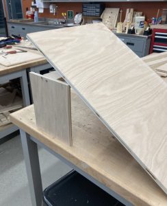
IMG. 1 – OLD RAMP
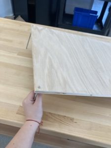
IMG. 2 – NEW RAMP
In addition to motor testing, I worked on the linear actuators (LA), testing them with an Arduino as we encountered issues with the code used to control them. Another key task I undertook was building a ramp for testing. Initially, I designed a standard adjustable ramp similar to a folding chair mechanism. This took about three hours to construct, during which I used M5 rods to lower the height and adjust the angle. After consulting an expert, I revised the design and switched to using two M5 threaded rods for better adjustability.
I am behind on this project with little time left, so I plan to dedicate significant time to working on the circuit, catching up, and putting in extra hours.
My main goal is to get the robot running and begin testing as soon as possible. I also hope to finish the ramp to test inclined angles and assess balance with water on top.
Sara’s Weekly Update (March 22, 2025)
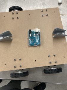
We are caught up with the physical build. The robot is currently designed for testing: a detachable platform to test for slop climbing, and a small linear actuator (LA) for platform testing. I drilled the L brackets onto the platform and the LA onto the board. I also completed the rest of the motor controllers to motor wires.
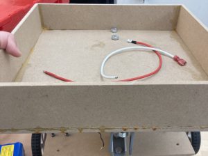
IMG 1. Completed Board and Platform
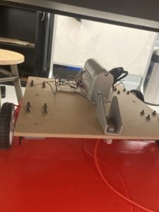
IMG 2. Completed Wheelbase with mounted LA
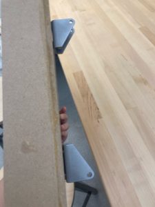
IMG 3. Added Mounts to platforms
I got our LA to run. Here is a link to the video. https://drive.google.com/drive/folders/1XDY6sC3153WC3wEnl2y9C_0TSnG_CBZb. During this part, I fried a motor controller… Sorry.
I tried to use yarn to stabilize our LA, did not work. We purchased a P-series mount to straighten the LA’s when the bot is going up a slope.
I am on schedule with the robot body, as we previously discussed that testing would be conducted in a different manner to accommodate a testing schedule for individual parts. I decided not to install the electronics yet since they are needed for separate component testing. To compensate, I plan to fully utilize this testing mode to make sure our robot works completely. This involved drilling holes in the platform for the mount, which could result in water leakage onto the board. I plan to glue pieces of wood to the platform and the bottom for added security when we add the different p-series.
However, we are behind schedule on the robot itself. While we have the code, we are rushing to complete implementing it. To compensate, we plan on working on smaller parts and combining them later.
Next week, I plan to assist Raymond with his work and continue testing the robot platform and its driving capabilities.
Team Update (March 29, 2024)
The most significant risk to this project is the power and the FPGA and IMu not communicating with the robot. We are having issues with plugging in multiple motors, which is causing the voltage to drop across all devices. This means we cannot continuously drive the robot on the slope. We are also having issues with imu outputting accurate data. We have managed this issue by using capacitors to increase the voltage, and we planned for this by using two batteries. We might want to get a battery with the same voltage but with a higher amperage output. For the imu, we are rewriting the algorithm to account for the calibrations. We want to get a better IMU for more accurate calibration.
At this point, there are some changes to the electronics as different motors have been purchased with a lower rpm to get a higher torque. This is needed to get the robot driving. We also might have to add some capacitors to the electronic design for more voltage, since there is voltage dropping and we constant voltage across all the motors. This has cost some money, but this is a completely easy fix when we get the motors.
Our schedule this week has primarily focused on testing the robot. The updated plan prioritizes testing the robot and its performance. Moving forward, our next steps include implementing these fixes, testing the robot under real-world conditions, and refining the overall system to ensure reliability and functionality.
Team Update (March 22, 2025)
The thing that jeopardized the success was not having the right cable. The code cannot run on the USB micro b wire. We found out that we could not connect with a normal micro USB and we debated on buying an expensive part. This means our code cannot be uploaded to the FPGA. We ordered a new one and immediately implemented code tested with Arduino. We are not moving away but improvising with this issue.
We decided to buy a P-series mount because we couldn’t find a way to straighten the linear actuators. The bracket is crucial for keeping the platform tilting properly. We spent nearly $40 on it. We plan to use our current design as a testing mode.
We pushed back driving the robot until next week because of our inability to upload the code. This is solved by testing the code on smaller pieces like the motor and the IMU, and p[reously said testing on an Arduino as a backup.
Raymond’s Status Report 3/22/25
This week, I made progress on implementing the motor control system using the Ultra96 FPGA development board. My primary focus was on configuring the Timer Counter peripheral to generate precise PWM signals for variable speed control of our DC motors. After examining the board documentation, I determined the appropriate pin mappings for routing the timer outputs to the external connectors where our motor driver circuitry will interface.
I spent considerable time analyzing the C application code that implements an interactive console interface for selecting different motor speeds. The code efficiently configures the timer hardware, sets up interrupt handlers, and implements PWM generation using the match mode functionality, which allows for precise duty cycle control without requiring constant CPU attention.
During testing, I encountered some unexpected challenges with the development environment. I discovered that our board was running a Linux image that prevents direct hardware programming, and that the Ultra96 requires a specialized adapter for complete debugging capabilities. While these issues have slightly delayed the implementation timeline, I’ve identified clear solutions. For the coming week, I plan to either acquire the necessary adapter or create a custom boot configuration, complete the hardware setup, program the FPGA with our control logic, and begin physical testing with the motor driver to validate the speed control functionality across different duty cycle settings.
Team Status Report for 3/15/25
The biggest risk factor is the robot being unable to move or the platform not working by the end of this week. Some things that may contribute to this problem are if the custom IP block for the IMU does not end up being useful. As a contingency plan, we may send the IMU data from the Arduino through UART, which should make retrieving and using the IMU data easier. Another concern is the speed at which our linear actuators move. The fastest rate for change in angle will be when the robot is driving from a flat surface onto a ramped surface, so we plan to slow the robot down if the linear actuators are unable to adjust quickly enough. Before, our systems for the wheelbase and the platform were independent, but we think that we could have the two systems interact to solve this issue. Another risk is keeping the pistons still. To address this, we plan on wrapping the axis with yarn to keep it still. As a contiguency, we might hot glue the yarn for more security.
We made the changes to attach the electronics using velcro tape instead of screwing them onto the base. This was done to save time on reattaching/attaching the electronics on the board. The cost is $9.51.
There is a huge schedule change. We plan on getting the robot moving, the platform tilting, and the bot moving by the end of next week so that we can test and tweak the system. We expect to run into many issues, so we made this change.
Completed the Wheelbase with Arduino
Raymond’s Status Report for 3/15/25
This week, I was working on getting the motors to react to the IMU sensor data. I first tried to access the sensor data using the PYNQ framework. I was able to successfully access the device, but was unsuccessful in retrieving any useful data from the IMU.


Compared to Arduino, where you can easily extract the IMU data by calling some methods, I have not found a solution for the FPGA yet. I have also looked into a few different projects on Hackster, working with FPGAs and driving motors. Our FPGA is a Zynq Ultrascale+ MPSoc, while the projects on Hackster drive their motors with a Zynq 7000 SoC device, so mapping the block diagrams has been a bit difficult. Also, I found another project that sends IMU data from an Arduino through UART, but for the Ultra96, it would need an additional UART module, so I’ve been a bit hesitant. So throughout the week, I’ve been trying to map the Zynq 7000 module to the Ultrascale+ module, to get the motor driven. I’ve also looked into designing a custom IP block for the IMU since there’s a similar project controlling the motor with an ultrasonic sensor that is typically used for Arduino and they had built a custom IP block.
Based on our weekly meeting, and our own expectations, I have fallen behind in getting the FPGA integration done. But, if we are able to get the motors reacting to the IMU data by the next week, and get a preliminary system built, we are expected to be back on track.
In the next week, I plan to design a custom IP block for the IMU to get the data to be used for driving the motor. By the end of the week, I plan to be able to drive the motors based off the IMU data.
Sara’s Weekly Update (March 15, 2025)
This week, I finished the bot’s body. I focused on attaching the sides to the platform. 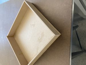
IMG.1 – Platform
I also finished installing the motors and wheels. (Note: Raymond is working with one of the motors, so our bot is a tripod.) Additionally, I drilled into the body and attached the mounts for the linear actuators.
IMG.2 – Wheel Base completed
Also, I made the wires for the motors to the Motor Drivers and the battery to the breadboard. The Arduino, which I got for free from Techspark, is for me to test the linear actuators using the motor controllers. I made them based on a drawing to keep them organized.
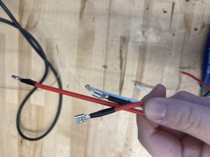
IMG.3 – The wires connecting the Motors and the Motor Drivers

IMG.4 – Motor Wiring Sketch
This week, I think I got what I wanted done for the body. I am behind on electronics since I decided to use double-sided tape to attach it. To catch up, I plan to prioritize securing the electronics first thing on Monday.
Next week, we need to get the robot moving and the platform tilting. So I plan on getting the electronics on the board and finish attaching the linear actuator, which takes two people. As a temporary solution, we’ll hold it in place with yarn. I also plan to assist Raymond with anything he needs.