Arduino Code Refinement
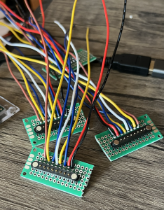
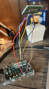
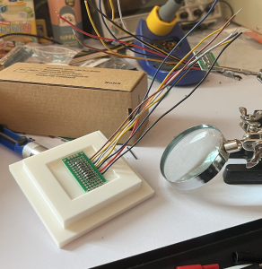
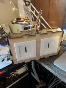
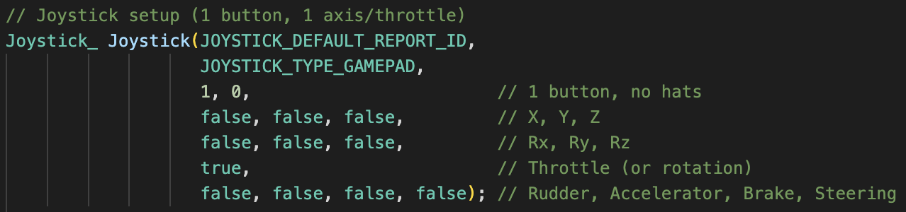
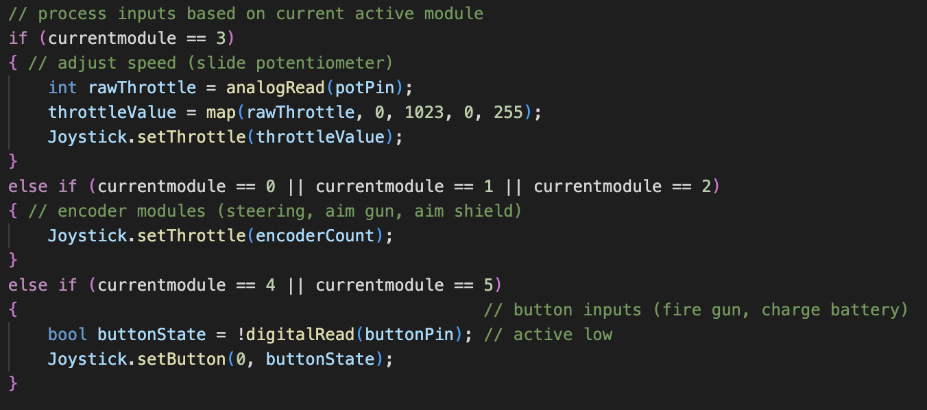
Since the final iterations of the modules and panels are all soldered and assembled, I spent this week refining the Arduino code to better integrate with Unity. The Arduinos are now able to simulate gamepads that have enough axes and buttons for each of the six modules. Unity is also able to see both panels separately and assign one of them to have harpoon gun and the other to have net gun.
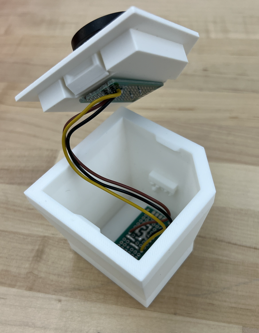
I also fixed bugs caused by users removing the modules while pressing the buttons. Previously, if a user pressed a button or turned an encoder while removing the module, the button would stay pressed and the encoders would keep turning in software.
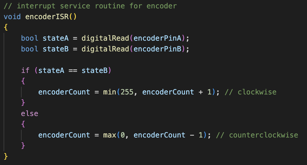
I added a smoothing function for encoder inputs to provide a more reliable user experience. Since some of the encoder state transitions would happen more quickly than others — even if the user was turning the encoder at a regular speed — I chose to take a moving average of the inputs. I used a simple, lightweight low-pass filter to achieve this:
// alpha is the smoothing factor
avgSteerSpeed = alpha * newSteerSpeedData + (1 - alpha) * avgSteerSpeed;
Playtesting
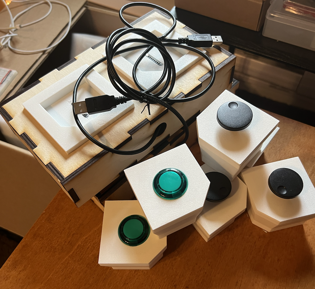
After finishing the software, I presented the game to a few people to playtest it. We got a lot of good feedback, mostly about the difficulty of the game and which modules were too powerful. Fortunately, many of the solutions to the feedback were straightforward. For example, most players felt that the submarine moved too quickly, and we can easily limit the maximum speed in the code.
Progress and Next Week’s Deliverables
Progress is on track for demo / final. I will spend the next week primarily working on the final deliverables.
As you’ve designed, implemented and debugged your project, what new tools or new knowledge did you find it necessary to learn to be able to accomplish these tasks? What learning strategies did you use to acquire this new knowledge?
Prior to this project, I had not worked extensively with Arduino. I knew the basics but not the intricacies. There were a few times when I didn’t understand why something was happening and couldn’t figure it out on my own. One of the learning strategies I used was looking for answers on the Arduino forums since many other people had the same issues before me. I also spent a lot of time reading documentation to understand details about the hardware, such as which pins can support interrupts and what pull-up/pull-down resistors are available.

 The ISR is attached using