I spent this week looking at different approaches to interface between the modules and the Arduino.
Module Pins
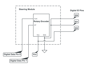
As a team we decided that each module would get Vcc and Gnd, 3 pins to identify the module, and up to 2 data pins per module. Using the identification pins instead of unique data pins per module allows us to reduce the total number of pins used which is beneficial since the Pogo pins we’re using can be expensive. This also reduces the total number of single points of failure. Each module will therefore have a unique 3-bit identification code. They will be wired as shown, with Vcc and Gnd driving the ID pins:
Debouncing
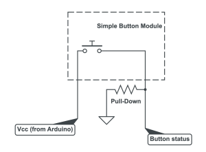
I also considered the problem of debouncing. We don’t want a single button press to be registered as many presses in a short period of time. I compared software solutions with hardware solutions and landed on a few different approaches. For the button-press module, a simple RC filter with a Schmitt trigger should work:

The RC filter smoothes the transition from LOW to HIGH and the Schmitt trigger replaces the single threshold voltage with two separate LOW/HIGH threshold voltages. This ensures that any oscillations near threshold voltages do not result in an oscillating output.
Progress
My progress is slightly behind since we just recently settled on the schematics and electronic components so I haven’t made the initial module prototypes. To catch up, we will place the remaining component orders soon and work with what we’ve got for the simpler modules.
Deliverables for next week
Since our Arduinos have shipped, I hope to have some working code that interfaces with hardware components by next week. Ideally we’ll be able to see a physical button press register in Unity software. I also hope to place the orders for the remaining electronic components so we can build all of the remaining modules.