Amelia’s Status Report for 2/15

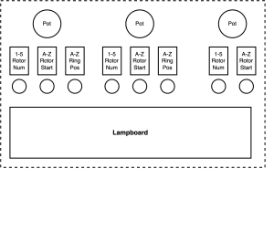
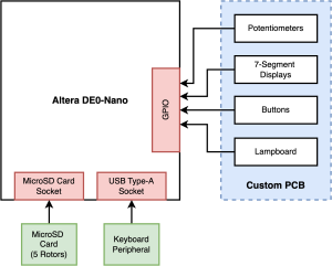
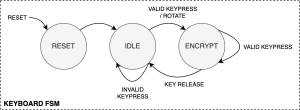
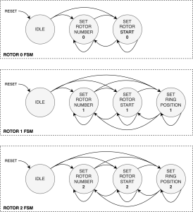
This week I mostly worked on designing our finite state machines for the rotor settings and for the keyboard (see below). I also redesigned the top layer view (see below) of our schematic (with potentiometers) after getting feedback from course instructors who advised that we should include a turning rotor mechanism (we decided in the form of potentiometers) to help mimic the look and feel of the original Enigma machine. I also redesigned our system block diagram (see below) by removing the Arduino after receiving feedback from our proposal. Now our design only consists of the FPGA, custom PCB, and keyboard peripheral. I also researched the Altera DE0 Nano board as a replacement for the Altera DE10 due to the increased number of pins we’ll need since removing the Arduino from the system. Lastly, I worked on the design presentation slides. 

Due to our redesign, I did not research UART like I had mentioned last week because UART is no longer needed since removing the Arduino. Next week I’ll work on finalizing the signals and modules for RTL encoding. Next week I will also likely spend quite a bit of time on the Design Report — this is because Nancy and Tanisha are working hard to finish the custom PCB to send to the fab before spring break.

Tanisha’s Status Report for 2/15

This week I continued to work on the schematic for our custom PCB. Due to some design changes I had to switch certain components out and ensure that the ones we maintained were able to work with the rest of our components. This required a lot of overhauling of current work (updating BOM and components list) which occupied the bulk of my work this week. Some of the new components included the external keyboard instead of building one on the PCB so I explored some tradeoffs in that area and looked at previous capstone projects that successfully used both options. The current decision is to work with a keyboard through the ribbon cable as opposed to the USB port which was the original reason why we ruled out the external keyboard option. I also updated our Gantt chart and planning schedule based on our new design so the work was evenly spaced out and accurate to the scope of our project.

Finally, I also worked on our Design Presentation slides and started preparing for the Design presentation in the upcoming week as I’ll be presenting for our group.

This week I plan to source further feedback on my schematic (have previously discussed with a peer and faculty on certain design choices) as well as presenting the Design Presentation. This should keep us on our updated schedule as the removal of the Arduino means I’ll be freed up to work on the external keyboard hardware and test it thoroughly.

Nancy’s Status Report for 2/15

This week, I researched into the peripherals we were considering using for our project and further refined the design. More specifically, we met with Prof. Chang on Monday, who suggested that we consider adding a small receipt printer to our design so that museum-goers could walk away with a copy of their encrypted message. I spent time researching into printers that could communicate via UART, and I found some resources that demonstrated using it for Arduino, which could be useful for implementing on the FPGA. Ultimately, we decided against the printer after having our weekly meeting, but the time spent researching more into the GPIO pins on the FPGA & UART protocol could be useful in the future.

Additionally, after receiving feedback from our proposal presentation, Amelia & I met to discuss how we could move more of our functionality onto the FPGA. We researched into the different FPGAs available to us, and saw that the DE0 Nano has 2, 2×20 GPIO pins, which would be sufficient for all of our peripherals given that we use shift registers. We also looked more into the documentation for the FPGA and evaluated whether we could use the existing micro SD card on-board, but decided it wouldn’t be feasible since it is reserved for boot-loading. After meeting with Tanisha as well, we decided that we could implement the entire design on just the FPGA.

I am on schedule since we are finalizing our design, the peripherals that we will use, and the communication protocols we will implement. This week, I help to finalize the design presentation, specifically refining the technical requirements with more quantitative values. I will also do further research into the microSD card reader and power consumption since moving fully to the FPGA, and will begin working on the PCB layout once the schematic has been changed to reflect our new design.

Team Status Report for 2/8

Up till now, we’ve decided on a basic PCB layout, designed the pipeline from custom PCB to arduino to FPGA and selected various appropriate transmission protocols. We decided on which modules would handle which tasks; PCB handling I/O, Arduino handles protocol translation and FPGA handles encryption and computation. We selected the Altera DE10 Standard Development board because we are most familiar with the board and its environment. We also worked on and submitted our proposal presentation. We finalised the existing system and pipeline with all major components researched (Arduino, FPGA, PCB).  

A risk we were faced with was the uncertainty of ordering components / our PCB from China due to the current trade and economic landscape. The uncertainty stems from lead time, increased costs due to tariffs and potential halts to postal services from China. To mitigate this, we plan to look into risk/cost tradeoffs with local suppliers. 

On Tuesday, we went on a field trip to see CMU’s very own Enigma machine. After asking a librarian at Hunt where the machine was located and coming up empty handed, we contacted Sam Lemley, the Curator of Special Collections at CMU Libraries. He informed us that both of CMU’s Enigma machines were currently on loan to the Heinz History Center, but one of the machines (the 3 rotor one) would be back at CMU this week. We met up with Sam this past Tuesday (2/4) and he gave us a hands-on demo and brief history on how CMU came to get possession of the machine. It was very exciting to see a real Enigma machine up close!

Nancy’s Status Report for 2/8

In the start of this week, I helped to finalize the slides for the design presentation, especially with refining the technical challenges and mitigations and relating them to the requirements we had defined on the previous slide. When our team met on Wednesday, Tanisha and I spent time discussing using shift registers for our keyboard and lampboard and further defined the peripherals we would need on our schematic. Later in the week, on Thursday and Saturday, I researched how we should power our design, which was something we received feedback on during our proposal presentation. We had decided that the FPGA should be plugged into a wall outlet, but were unsure about what to do for the Arduino. Having to consider power consumption is something that I have not done a lot before, and took a good amount of time researching the basics, which I summarized in the attached document. Ultimately, I decided that we should use rechargeable AAA NiMH batteries with an Adafruit PowerBoost 500 Basic, which is a DC/DC boost converter. While it requires more work to integrate with the Arduino than a 9V battery connected through the power jack, it will last longer. I also considered a rechargable LiPo battery with a similar converter, which would have a greater capacity, but I liked how using AAA batteries is more accessible and is less of a fire hazard that would need to be mitigated for use in a museum or classroom.

My progress is on track since this was an important aspect to decide on as we start designing our PCB schematic. I will continue to work with Tanisha next week on reviewing the exact parts we selected for our PCB and verifying the schematic before I start on the layout. I will also work on summarizing the work we’ve done on the embedded side of the project that we can include in our design presentation.

Amelia’s Status Report for 2/8

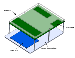
This week I started and finished the slides for the proposal presentation and practiced for and gave the presentation. I also researched and planned out the physical design of our Enigma machine and used CAD to plan out where our various components — PCB, Arduino, power supply, and FPGA — would be positioned on the board and how they would be connected. The custom PCB will be mounted above the FPGA. The Arduino will be mounted below the PCB using header pins. The power supply will be connected to the Arduino and mounted on the bottom plate of the Enigma machine. I also designed an acrylic cover to be mounted above the PCB. Half of my time this week was spent refreshing myself on how to use SolidWorks.

As for the project schedule, I was meant to CAD the design at the very end of the semester, however, we realized that we needed to CAD our design much earlier in order to visualize how the components would fit together. This required rescheduling my tasks, but I believe I am still on schedule. Next week I will start planning out and writing the RTL. I will design our UART protocol and start implementing it. I’ll also start working on our design report and design presentation slides.

Tanisha’s Status Report for 2/8

This week I worked on creating the components list for our PCB. This included researching all the relevant components, finding footprints, and all but ordering the parts. Components included the Arduino SPI interface with SD cards, SD Card readers, 7 Segment Displays, encoders and decoders (which we’ll be using shift registers for) and all required LEDs, resistors and buttons. We pivoted from using encoders to shift registers and single 7 Segment Displays to the Max7219 which took a bit of adjusting on our planned Arduino pin layout. I looked into lead times and shipping costs to decide where we would be ordering from for each of these, made sure it fit in with our planned schedule, and updated the BOM. I’ve also started a barebones schematic and reached out to a third party for peer reviews. This fits in with the scheduled plan as I should be on track to send out the schematic this weekend and get feedback and iterate by next weekend.

Components:

BOM: