Two weeks ago we had our Interim Demo and received good feedback from this. We presented a working encryption scheme with inputs on the PS/2 keyboard and output displayed to the FPGA’s 7 segment display and using the FPGA switches as rotor dupes, a printout of our PCB with components laid out (since PCB was still being manufactured), and a presentation with our updated use case, design, and schedule. We felt that this Demo went well and based on feedback plan to update our final Demo to have 2 separate models – one with only the FPGA and one with both the FPGA and PCB to show off all the work we have done till now.
This past two weeks Amelia and Nancy worked hard on the rotary encoder RTL, wrote the entire SPI protocol for the MAX7219 7 segment display and integrated the encryption modules to work with all of the GPIO RTL they have written over the past few weeks and got everything working successfully!!
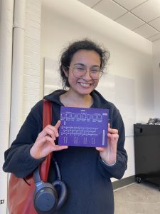
This week the PCB arrived (yay! see attached picture!) so Tanisha fabricated it and soldered all the SMD and PTH components on excluding the rotary encoder. Once that header arrives on Monday, she can solder it and the PCB fabrication will be complete. This week she will work on testing the PCB, completing her final report tasks and starting preparation for the final presentation.
For validation we will test our integrated system against results from each of our modular subsystems continuing on from our individual verification tests.
Meanwhile, the Verilog team will work on integrating the rotary encoder with the rest of the RTL and writing the RTL for the lampboard shift registers.
After the RTL is complete, the whole team will work on integrating the PCB with the RTL, carrying out user testing and planning the final demo set up. This all fits in to our planned schedule!