
What did you personally accomplish this week on the project? Give files or photos that demonstrate your progress. Prove to the reader that you put sufficient effort into the project over the course of the week (12+ hours).
- I built the circuit for the RPi on the breadboard for testing purposes. This included the pogo pins, LCD (for row category display) and button (for answer submission).
- I also tested the components we received including the pogo pins, regular LCD for row category display, RGB LCD for block word display and the button individually to make sure they were working well as expected. For the button, I utilized the RPi built-in GPIO functionalities to detect the button press by using a callback function. For the regular row category LCD, I utilized the Sparkfun QWIIC SerLCD library to interface with the LCD, allowing me to change the backlight color (when we display the answer) and the text on the screen. The RGB LCD for block word display was purchased from Waveshare and there were starter codes found on the Waveshare website which I referenced to set up the interface between the LCD and the Pico.
- I also worked on implementing a basic UART communication between one RPi and one Pico via the pogo pins. To program the Pico, I installed Thonny on my computer in order to program the Pico using MicroPython. On the Pico, I utilized the machine library to read from the UART pins of the Pico. On the RPi, I utilized the pyserial library to read from the UART pins of the RPi.
- The main issues I was concerned about were transmission latency and accuracy. It seems like latency wasn’t an issue because one cycle of transmission (including sending and waiting for ACK) includes a 100ms delay. This will ensure that in the worst case scenario a block is not present, the RPi will detect this within 300ms. In the future, I might adjust the delay time period to allow for faster communication between the RPi and the Pico. In terms of transmission accuracy, I encountered issues where the Pico would not receive the entire word from the RPi or it might mistake a word that was transmitted twice to be a singular word. As such, I implemented a format for the data sending, by prepending all game words with “#” and all queries with “@” so as to differentiate between the two commands. I also added data parsing to extract the words and commands accurately. I used the highest baud rate of 115200 and managed to achieve accurate transmission between the RPi and the Pico. I simulated the entire game loop by having the RPi send a word to the Pico. (The Pico received the word usually on the first or second attempt by the RPi). Following this, I simulated the RPi querying the Pico for the word and the Pico was able to successfully transmit the word to the RPi and the RPi also changed the text on the row LCD.

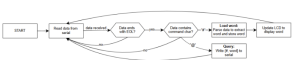
- I also created an FSM diagram to showcase the different states within my program.
- I also asked Quinn about the PCB Milling Machine and came up with alternatives.
Is your progress on schedule or behind? If you are behind, what actions will be taken to catch up to the project schedule?
- My progress is on schedule and I have completed most of the prototyping for one block interface, except for displaying the word on the block’s LCD.
What deliverables do you hope to complete in the next week?
- Next week, once the Picos arrive, I hope to experiment with the testing of 2 and more block circuits. This will involve the use of the multiplexer.
- I also hope to help with the construction of an actual block once the acrylic blocks arrive. The block would consist of a perforated board with the connections soldered to connect the Pico to peripherals such as the LCD and pogo pins (for UART)