
Verification and Validation Update:
As we transition into the verification and validation phase, we are aligning our testing approach with our core engineering design and use case requirements. I am mainly in charge of the dashcam circuit components so my individual testing are more oriented with the dash cam power supply system.
Our dashcam power system is designed to draw power from the car’s cigarette lighter, which is converted by an adaptor to 8.4V 2A for the UPS(Uninteruptable Power Supply). The UPS then regulates this input to provide a stable 5V 5A output to the Raspberry Pi, while also managing seamless switching to its internal battery when the car is turned off—ensuring a safe shutdown process for the RPi.
Tests Completed:
- Power Regulation Test: Verified that the adaptor consistently provides stable output (8.4V ± 0.3V and 2A ± 0.2A) under both nominal and surge input conditions to the RPi UPS module.
- UPS Power Supply Test: Verified that the UPS consistently provides stable output (5V ± 0.3V and 5A ± 0.4A) under both nominal and surge input conditions from the simulated power supply from car. Also I tested and verified that the UPS consistently provides stable output when the power supply simulated from the car is off, which means the UPS switched to its battery for backup power supply.
After verified the system works during simulation test in the lab, I tested the system on a car with actual car cigarette lighter.
- In-Vehicle Test: Validated system stability in a real car environment with varying RPMs and load conditions. Continously measured the voltage for 5 min while another driver is driving the car under normal driving condition.
Verification Approach:
- Instrumentation: Use multimeters, current clamps to monitor real-time voltage and current waveforms.
- Simulation: Use voltage generator from ECE labs
Planned Tests:
- Endurance Test: Run the complete system for an extended period to test long-term reliability, focusing on consistent voltage and system uptime.
- Integration Test: Connect with RPi to conduct end-to-end testing for the entire system while continously measure the voltage and current to check for abnormal circuit behaviors.
Summary of Work This Week:
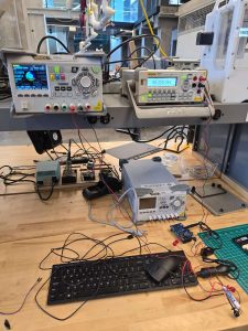
- Cigarette Lighter to Adaptor Simulation Testing:
- Used a wire-to-car-cigarette-lighter converter to simulate a car’s power source.
- Connected our adaptor to a breadboard to measure voltage and current under standard conditions.
- Confirmed that the adaptor correctly regulated the voltage from the car cigarette lighter.
- Simulated transient input spikes ranging from 10V to 20V, which can occur due to vehicle alternator behavior or load switching.
- Verified that our adaptor provided clean, regulated power even during input fluctuations.
- Raspberry Pi UPS Power Test:
- Used the stabilized adaptor to power a Raspberry Pi UPS HAT.
- Disassembled the RPI and UPS HAT for isolated testing.
Next Steps and Schedule:
- Continue full integration testing with the RPI in-vehicle.
- Monitor long-term stability under varying driving conditions.
- Begin logging power behavior during startup and shutdown phases.
Progress:
This week, I made progress by completing the majority of the circuit-level testing. I verified the power regulation behavior of our adaptor and UPS module, both in simulation and in a real vehicle environment. With these components confirmed to be working, we are ready to move forward with full system integration using the car cigarette lighter as the actual power source.
Additional tests, including endurance and thermal testing, are planned to further ensure reliability under extended and realistic conditions.