Rebecca’s Status Report for April 26, 2025

Report

I spent a good chunk of my time this week (the vast majority of Sunday, ~8hr) working on the final presentation, and then since my slot ended up being on Wednesday, I spent a few more hours on Tuesday night reviewing the work and polishing my spoken words (though the slides of course had already been submitted). Then yesterday and today sunk a significant amount of time into writing the poster, and assembling a list of unit and integration tests for the team status report. Writing words takes so much time.

I soldered together the power lines and re-did the I2C one more time after I realized that the iron I was using last time wasn’t just oxidized, it was corroded and actually damaged, so it wasn’t transferring heat well. It went much smoother, and now the I2C connection isn’t intermittent at all.

The frame finished printing pretty late tonight, since unfortunately the first time I printed it I didn’t give the front piece enough support so it collapsed partway through, and then I got caught up in another class’s work so it took awhile to get it restarted.

It looks like there’s just one hole that didn’t cut clear enough for the machine screws to go through on the first shot, but it’s clear enough that I should be able to force it in/cut away the material with minimal effort. I had to put a lot of support under the two upper battery prongs (not very visible from the photo’s angle), so I’ll have to come back with someone else tomorrow and cut it away with the Dremel (don’t use power tools alone, etc.). I’m not going to install or epoxy anything together until that’s done so it’s not more difficult or more dangerous than it needs to be, so now I go to sleep.

Progress Schedule

There’s not really any schedule anymore, these last two weeks were deliberately left open for “crunch crunch crunch get anything left to be done done now” and that is. Just what’s happening.

Next Week’s Deliverables

Poster, video, demo, paper. In that order.

Rebecca’s Status Report for April 19, 2025

Report

I spent much of this week finishing the CAD for the headset. It takes so long. It really takes, just so many hours, and since it’s got lots of small details at weird angles I had to think so much about printability. That said! He’s done, basically, with the exception of a few measurements I approximated with my tape but would really like to get a better number on with The Good Calipers that live in my org’s shop. Which I will go out to at a time that is not some bitter hour of the morning when look I am simply not leaving my dorm. So!

As I said last week it’s in several parts to make it easier to print. I’ve also decided to use some parts of the original casing my display came in, particularly the parts that mount the optical lens and the screen together at the right angle, since trying to replicate its details in an already-complicated print at what would have to be a suboptimal angle would be very prone to printing problems. Like the sidebars, I’ll be able to attach the several front pieces with a combination of the original display casing’s screws and a small amount of epoxy.

I also intended to attach the display to the Raspberry Pis, but when I wired it together by hand I did the I2C for the early tests, it… didn’t work. It lit up with a blank blue screen when I powered it, sure, and I was easily able to get the brightness control lines to work as expected, but when I actually connected the AV data input line to the Rasppi’s AV output while running a very simple test frame generation script, the screen just went dark.

There are several things that could be wrong.

  • The Rasppi isn’t outputting the right format.
    • Unlikely. I tried with my Rasppi configured for all three major standards, and none of them worked.
    • There are three major standards for composite video: NTSC, PAL, and SECOM, with North America generally using NTSC. It’s the default for the Raspberry Pi along with most devices, and the standard I understood this display to use.
  • The Rasppi isn’t outputting at all.
    • Possible? This device’s configuration is persistently obscure and arcane, so it may be a configuration problem. I used an oscilloscope to detect the waveform on the AV test pads, and it appeared to be what would be expected for a solid black screen. So maybe not just that there’s no signal at all, but maybe:
  • The Rasppi isn’t outputting what it should be outputting.
    • Also possible. It’s a known but that when using an HDMI peripheral with a Raspberry Pi board, sometimes if the device isn’t attached when the board boots up it just won’t recognize when the attachment occurs. I wasn’t able to find anyone saying this is also true with the AV output, but then, I wasn’t able to find really much discussion of the AV output at all.
    • Also a note in this or the previous possibility’s favor: the same behavior occurred when the AV was configured entirely off.
  • The Rasppi isn’t outputting in the right resolution.
    • Technically possible, but unlikely. NTSC is 720×480, and that’s what the Rasppi generates when configured therefor. The display is nominally 640×480, which I thought was the screen output and not the resolution input, since NTSC is a standard and if you’re going to claim your device takes composite input, it has to take it as a standard. Honestly I don’t even know how I would detect this. Nobody makes tools that output 640×480 composite, because that’s just not a thing. I’ve seen this exact device work with an off-the-shelf HDMI-AV converter, so surely it’s not some obscure custom resolution type. How would you even do that, it’s an analog signal.
  • The signal is getting corrupted between the Raspberry Pi and the display.
    • Unlikely. I ran ground twisted with the signal on a very short wire in a relatively low-noise environment. A corrupted signal would at least sometimes show me a couple colors that aren’t solid black, I think.
  • The display is broken.
    • God, I hope not.

I’ve already done some amount of testing to get to the approximate likelihoods as described above, and have more to do early next week when the tools I ordered to help my debugging (RCA AV cable, HDMI-AV converter) arrive. Those tools will also help me build workarounds if the issue cannot be entirely fixed.

I’ve also spent a bunch of hours mostly today and yesterday writing the slides and script for the final presentation.

Progress Schedule

With the completion of the CAD, only a few more steps remain in building the hardware- printing, cutting the mirror and acrylic lenses, and assembly. My machine screws even arrived early. There’s a little bit more testing to be done on the communication between the camera’s Rasppi and the display’s, with the I2C mostly working, but then the on-headset data communication will be complete.

I’m running behind all-around, especially with this AV issue cropping up, but I don’t think it’s irrecoverable yet.

Next Week’s Deliverables

Fixing or finding a workaround for the AV problem is my first priority. Additionally, writing the final paper is going to take a significant amount of time. Then assembly. All of the devices can be hooked up and tested working together before they’re mounted.

Verification & Validation

I accidentally wrote up this week’s additional response last week instead of the intended one (oops), so this week I’m filling out last week’s. I’ll probably come back and switch them when I’m cleaning up my links and such so at least they’ll be in the right place eventually.

Subsystem verification tests:

  • I2C communication
    • Small messages (a byte, the size of our real messages) sent five times per second over the I2C line to determine how solid the connection is, though it’s known to be somewhat faulty. Four-in-five returned acknowledged, on average, which is more than I had the first time I tried a similar version of this test with another method, but I believe this is more accurate since it uses the real messaging methods that my I2C library provides rather than just i2cdetect, which may have had an artificially low success rate due to timing weirdness in the clocks. I’m not sure. I wasn’t able to replicate the low rate again.
    • Messages replicating those that the algorithm run by the camera board will trigger sent manually to the display board, to test its responsiveness.
    • The whole on-headset system, with the wrapper on the MediaPipe algorithm sending I2C messages (mediated by a debouncer, so it doesn’t send a ton at once before the user processes the update has occurred and removes their hand) which are received by the image generation script and used to modify the display output.
      • This one hasn’t been run yet, but I plan to time it as well using the Rasppis’ real-time clocks to ensure we hit our latency requirement.
  • AV communication
    • All my problems with this are described above. These are tests I have or will run in an effort to debug it.
    • Oscilloscope to make sure there’s output on the pad (as expected for solid black, not what should be in the image buffer).
    • Run it with different standards, and with AV entirely disabled (no behavior difference).
    • Run it with the AV device already connected before power on (will require additional hands).
    • Run the AV output to a known-functional AV device (the TVs in my dorm house take composite, and I’m shortly to get my hands on an RCA cable).
    • Run HDMI output to an HDMI->AV converter board, which itself is connected to the display (only maybe necessary- possibly part of a workaround if it’s the Rasppi I absolutely cannot get it to output what I need).
  • CAD print
    • Test print with some mounting points available. Mostly to see how accurate my printer is at fine details, and make sure my measurements at the margin of error I expected were good. Outcome was positive, despite the poorly designed print triggering a lot of support structures being necessary.
  • Recognition algorithm
    • Pipe the camera output with the MediaPipe landmarks identified as an overlay to my laptop screen (X-forwarding through my SSH tunnel) to see what it’s doing, make sure it’s doing what I expect.
      • Used this to identify the source of the initial extreme fall-behind, before I forced a ceiling on the frame rate (and fixed the camera interpreter settings).
    • Run the full recognition algorithm at very low frame rates and raise it slowly until it cannot keep up; i.e., its own reported frame rate drops below the nominal one delivered by the camera. We want to keep it at the edge of functionality but not over, because pushing it too far tends to trigger overclocking (sometimes okay in short doses, very bad on long loops: causes overheating, ultimately slowdown, very high power draw, shortens the lifespan of the processor).
  • Display
    • Most of the display design was done by Charvi, so she did its verification tests. I set up the HDMI output so she could see the actual images as she went before we had the display attached (mostly before we had the display at all, actually).
  • Battery life
    • Run the Raspberry Pis with the scripts going on battery power from full charge for at least an hour and a half, make sure it doesn’t die. The power draw from the scripts, based on their design, should be relatively constant between nothing happening and actual use. Additionally, I expect the peripheral devices to draw a marginal amount of power, and this already accounts for power supply/boost board inefficiencies, so an extra half-hour over our spec requirement is certainly enough to ensure that with those extra parts it will still be enough.
      • Also, ensure the boards do not rise above comfortable-to-the-touch. Since we’re strongly avoiding overclocking, I do not expect it to.

System validation tests for the headset:

  • Run all the devices (including peripherals) for at least an hour, with periodic changes of environment, gesture inputs.
  • Time the latency from gesture-input (marked by when the camera registers the first frame with a given gesture) to display-update. This is referenced above from one of my verification tests. The setup in order to take this time will greatly resemble that.
  • Use the device for an extended period of actual cooking.
  • User comfort-survey; have other people wear the device and walk around with it, then take their rating out of five for a few points (at least comfort and interest in trying real use; probably others as well).
    • If the users are interested and willing to give us a more detailed holistic review we may allow them to actually use the device, but since this depends on their short-term available time and resources, we will not be requiring it.

Rebecca’s Status Report for April 12, 2025

Report

I corrected the soldering issue on the I2C pins as best as I could, and while the connection is still inexplicably intermittent, it’s consistent enough that I feel like sinking more time into fixing it is not worth the cost and there are better things I could be doing. We’ll have to account for the fact that when messaging over I2C it may not go through the first time you try with the software, by giving it multiple attempts until it receives the correct acknowledgement. As the amount of data being sent is minimal, this seems to me like a fairly low-cost workaround.

Additionally, since the first 3D print of the headset itself, I’ve reworked the design of the CAD into three parts- the front and the sidebars- that will all print flat, which is simpler, lower-cost, and will not require cutting away so much support material after the fact, which was a major problem in the initial design. I plan to attach them after printing with a small amount of short work-time epoxy resin at the joints. Additionally since the display came in the week of carnival, I’m working on the mount for it and the battery, as well as the power management board. I worry that because of the battery being mounted at the front of the headset, the device will be very front-heavy, but believe that this is the best of the options I considered, which are as follows:

  • Mounting to the front-middle, over the brow. Front-heavy, and also places the battery fairly close to the user’s face. I don’t expect the battery to get hotter than somewhat warm, so I don’t think this is a problem.
  • Mounting to one of the sides, which would make the device side-heavy. I believe that side-heaviness, asymmetry across the human body’s axis of symmetry, is more difficult to deal with and more uncomfortable for the user than front-heaviness.
  • Mounting at the rear of the head, from, for instance, an elastic that attaches to the headset’s sidebars. The battery is light enough that acquiring an elastic strong enough to support it would be possible. However, this demands that the power lines between the battery and the devices on the headset be very long and constantly flexing, which is a major risk. The only mitigation I could come up with would be making the stiff plastic go all the way around the head, but this severely constrains the usability.

So to the front of the frame it goes. If it proves more of a difficulty than I expect, I will reconsider this decision.

Progress Schedule

My remaining tasks, roughly in order of operation:

  • Finish designing the mount for the display on the CAD.
  • Print the CAD parts and epoxy them together.
  • Solder the display wires to the corresponding Rasppi and run its AV output.
  • Purchase machine screws and nuts to attach the devices onto the frame.
    • I need #3-48 (0.099″ diameter) screws that are either 3/8″ or 1/2″ long, and nuts of the same gauge and thread density.
  • Purchase car HUD mirror material for the display setup.
  • Cut clear acrylic to the shape of my lenses.
  • Solder together the power supply (charging board & battery).
  • Solder the Rasppis’ power inputs to the power supply.
  • Mount the Rasppis, camera, display, and power supply to the headset.

Next Week’s Deliverables

Pretty much everything as listed above has to get done this week. As much as absolutely possible.

Also, the slides and preparation for the final presentation, which I’m going to be giving for my group.

New Tools & Knowledge

I’ve learned how to use a great deal of new tools this semester. I’d never worked with a Raspberry Pi before of any sort, only much more barebones Arduinos, and just about all of the libraries we used to write the software therefore were also new. I learned about these through the official documentation, of course, but also through forum posts from the Raspberry Pi community, FAQs, and in a few cases a bit from previous 18500 groups’ writeups. I’ve used I2C before, but only with higher-level libraries than I had to use this time, because I had to manually set up one of my Raspberry Pis as an I2C slave device.

Also, my previous knowledge about 3D printing is minimal, though I’ve worked with SolidWorks and Onshape before (I’m using Onshape for this project). I learned a lot about how it works, how the tools work, the tenets of printable design, and so on, kind of through trial and error but also from some of my mechanical engineer friends who have to do a great deal of 3D printing for their coursework.

Rebecca’s Status Report for March 29, 2025

Report

I soldered pins into the I2C GPIOs on the Rasppi boards to make accessing them simpler. With a steadier metallic connection I was able to test the Python version of the I2C library and got it to work as well, which makes wrapping the core code on each of the boards in the communication harness necessary much simpler since it’s all in the same language (and also I have an example of it working events-based, instead of just polling on every loop, so I don’t have to fight through figuring out events-based code in C++). I measured the current draw of each of the Rasppis running their core code, so I know how heavy of a battery I need to purchase, and it actually turned out to be a little less than I expected it to be. 1200mAh should do it; I’ve put in an order for a 3.7V LiPo that size (I think? This week has been a little hazy in general. If not I’ll do it tomorrow, either way it should get ordered early next week) and I have a 1200mAh LiPo battery on hand from a personal project that I can start to work with and wire things to on a temporary basis before it arrives.

Also the display arrived! As I understand it it arrived on time (March 22) but I didn’t actually get the ticket from receiving until much later in the week since the original one went to the wrong email (one attached to my name but on the wrong domain, and which I thought had been closed. Oops). But I have it now. It’s here! I feel so much less terrified of this thing now that it’s here! I need to get my hands on a reflective surface (will probably just order little mirror tiles and cut them to size, or a reflection tape that I can stick to the same sort of acrylic plastic that I’m going to cut the lenses out of. Gonna see what’s cheaper/faster/etc on Amazon).

I modified the draft of the CAD so I’ll be able to mount the Rasppis and the camera to it for interim demo. I ran out of time to do anything else, because the rest of the things are more complicated and the display came too late in the week for me to fight with it this week.

Progress Schedule

Things are getting done. I don’t know. It’s Carnival week and I am coming apart at the seams. I will reevaluate after next Sunday.

Next Week’s Deliverables

Interim demo. That’s it. I plan on printing the headset and attaching the boards I have tomorrow, and then I’ll have the wire lengths to connect the I2C pins. It’s gonna. get done


Rebecca’s Status Report for March 22, 2025

Report

I’ve got HDMI output working from the Rasppi without a camera. As per the usual, everything that could go wrong did go wrong, and I spent an unfair amount of time troubleshooting. The display was meant to arrive today (March 22) so in theory, if it did, I’ll get word about it from the receiving office on Monday. I’ve got access to a device that takes AV input, so if it isn’t here by then I’ll put in an order for an AV cable, cut an end off it, and solder the free wires directly to the Rasppi’s test pads. Then when I need to hook it up to the final output I can just cut the cable again to get necessary length and bare the other end of the wires. I might end up with a little more insulation than I was expecting, but really I can’t imagine it’ll be anything more than marginal.

I’ve been working today (and will return to working on it after I finish this writeup) on getting the Rasppis to be able to talk to each other over I2C. In theory it’s possible, but since their default settings are strongly weighted toward being I2C masters getting one to act as a slave is proving inconvenient (as per, again, the usual), though every document and forum post I’ve found more recent than 2013 is holding that the hardware is capable of it and the software exists to make it happen. Worst case I resort to using the GPIOs as GPIOs and just manually run a barebones protocol for the communication, which I think should be fine, considering we are not running more than like, a single byte a handful of times a second across the line.

Edit, two hours later: it works!!

Currently the slave device is running C code that consists of an infinite loop constantly monitoring for messages. I’d like to swap this out for Python (for language consistency) that does event monitoring, to reduce the loaded power consumption. The wires between my two boards are NOT soldered in right now, which feels… suboptimal, but hey, whatever works. Or works sometimes, I guess.

Progress Schedule

I’ll do my best to get them talking to each other tonight; if I can’t, the display arriving becomes my real hard deadline. They are talking.

I also really actually need to order the power supply this week. It is still very much on my radar.

Next Week’s Deliverables

If I can catch just a teeny tiny bit of luck at least one of my displays will have actually arrived this weekend and I can pry it apart next week. Then I’ll only be sans the power supply for things I have to order, and can put all of the things together if only powered by my laptop.

Rebecca’s Status Report for March 15, 2025

Report

Changing the WiFi on a Raspberry Pi without entirely rewriting the OS (using the imager) turns out to be a relatively straightforward task, assuming you have current access to the OS. Changing the WiFi on a Raspberry Pi without entirely rewriting the OS while you don’t, i.e., when you’re on the opposite side of the state to the network it’s set up for, is virtually impossible. It didn’t used to be, though- on previous versions of Raspberry Pi OS, pre-Bookworm, it was just a matter of creating a specific file in the boot directory of the SD card and putting the network information there in a specific format. And since so many people in the Rasppi community simply do not like to call out by name the version of the OS they’re working with, it took a frankly unreasonable amount of time to figure out that that method had been deprecated on the version I’m using, and that’s why it wasn’t working. (In fairness, I suppose, the new version of the OS is very new, only a few months at time of writing, so the vast majority of the discussion out there predates it. Unfortunately, the new version of the OS is very new, so the vast majority of the discussion out there predates it!)

CMU-DEVICE requires registry using the device’s hardware address, which is easily identifiable with arp -a on my laptop’s terminal given that it and the Rasppi are on the same network, I know the Rasppi’s IP address, that the two had been recently in contact. What I ended up doing was flashing my second SD card with the WiFi information for my cellphone’s hotspot, connecting both it and my laptop to that hotspot, using an IP scanner to identify the Rasppi’s IP address, pinging it, and then calling arp to get the MAC address. Success. My device is registered with the WiFi! Now how do I get to the WiFi? It’s no longer something stored on the hardware- I need to modify the SD card with all of my work on it from last week without destroying it.

There’s no good way, turns out. I ended up changing the login information of my phone’s hotspot to spoof my home network so the Rasppi would connect to it, then sshing in on that network to use rasppi-config to update the information. It felt very silly, but it worked, so sure! Alright! In retrospect, if I had started by spoofing the old network I could have skipped using the other SD card entirely, so if I have to change the information again going forward that’s the way I’ll do it.

My week has been… nothing short of insane, on account of one specific project I have in another class that ate me alive, so I haven’t gotten a chance to sit down in front of a monitor that takes HDMI or wire up the Rasppis to be able to talk to each other. I’ve done a good bit of research and am pretty sure I know how to make the I2C, HDMI, and AV out work, so RF project willing I’ll be sitting down early this upcoming week to get at least temporary wires running between the Rasppis. I’ll probably have to solder them in, since the boards don’t have pins, but I’m going to try to do the lightest-weight job I can since I’ll have to take it out and redo it eventually. I also realized that I need to get my hands on another USB Micro cable, since I only have the one but will have to test-power both of them at once pretty soon. Gonna ask around to see if anyone I know has one that I can borrow lying around this weekend, then just order one on Amazon early next week if not.

Progress Schedule

Unfortunately the radiofrequency project that came out of left field (I knew it was coming, didn’t expect it to be nearly so insanely difficult as it was) has put me on the back foot with regard to literally everything else. I might have to abbreviate some of the HDMI work I was planning on doing since we are approaching pretty quickly when the displays are going to be delivered. Gonna be playing catch-up this week.

Next Week’s Deliverables

I need to get the boards talking to each other, which may be early this week or may be late depending on whether or not I can get my hands on another USB micro cable quickly or not. Also want to get HDMI out working, since that was supposed to be this week and ended up falling to the wayside.

Rebecca’s Status Report for March 8, 2025

Report

I have learned that despite being supposedly a very mainstream device, the Raspberry Pi is… remarkably unintuitive. I’m using Raspberry Pi OS Lite to run the Rasppi headless and ssh into it, though for an as-of-yet unclear reason my computer does not seem to be able to resolve the Rasppi’s hostname and I have to use the IP address directly. This has only worked for this week’s development because I have direct access to my router and its IP address assignments at home, and will immediately have to resolve this issue upon returning to campus. Figuring out how to get into the Rasppi took just far, far too long because every single tutorial and answered question and Guide To Headless Rasppis that I could find online assumed that you could resolve the hostname, which is a very reasonable assumption, and simply bizarrely untrue in my case. I don’t know.

The Raspberry Pi OS Imager also doesn’t tell you what the name of the OS you’re using is, and even on the main website it’s just kind of… a throwaway inline parenthetical comment. Despite being the main thing the entire community uses to refer to the major versions of the OS. And so many things changing between them. It’s. This was a conscious decision. Why would you do it this way.

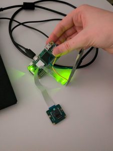
After figuring out the issue and getting into the board, getting it to talk to the camera was relatively simple (though I had the cable in upside down for a bit, which was deeply frustrating to discover after an hour and a half of debugging. So it goes). I’m using the native Raspberry Pi Camera Module, which is, you know, supposed to be the native camera and therefore straightforward to use, but you would just not believe the number of problems I have had because I’m using a native Pi camera instead of a USB camera.

First photograph captured from the Pi camera! It’s blurry and poorly exposed because I’ve left the protective plastic tab over the lens, since it still has to travel back to Pittsburgh. I expect the quality to be better once I take that off.

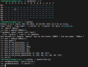
I also discovered that OpenCV’s primary image capture method VideoCapture(camera_id) is not compatible with libcamera, the regular Raspberry Pi camera library, because of course it isn’t. Surely nobody would ever want to use OpenCV straightforwardly on a minimal Raspberry Pi. Surely that couldn’t be an extremely common desire and mainstream goal. Can’t imagine.

However Picamera2, the Bookworm Python wrapper for libcamera, is configurable enough to be kind of compatible itself with MediaPipe.

(As an aside: all of the libraries I used this week I was able to access via pip, and that also seems to be the simplest way to use MediaPipe, except for Picamera2, which was only accessible with apt; I set the include-system-site-packages flag in my pyvenv.conf to true to be able to use it.)

This is the MediaPipe on Raspberry Pi tutorial I started from. It doesn’t work on its own, because it relies on the OpenCV method that doesn’t work, but I used it and the associated tutorials linked to set up the Python environment (sigh. why did it have to be Python) and MediaPipe installation.

I found this document, which was exactly what I want to do, with the sole caveat that it’s ten years out of date. Picamera has been displaced with Picamera2, which has been significantly streamlined and so the translation isn’t 1:1, and I’m not familiar enough with either library to do a quality translation. Sigh.

I ended up being able to scavenge bits and parts from this document and from the Picamera2 repo examples to make an trial script which captures images off the camera and streams them via OpenCV (in this case over my ssh tunnel, which was very slow, but I hope an amount of that is the ssh streaming and it will speed up when I cut that).

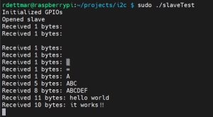
I was able to then graft the working Picamera image-capture script onto the MediaPipe script provided in the first tutorial. I’m just using a generic model right now, not our own custom gesture language, but it is a proof that the software works on the hardware. If only just barely. It ran at this point extraordinarily slowly, and there was truly just an untenable amount of lag between my hand motions and what I saw on the screen, and even more between the motion of the frames on the screen and the MediaPipe overlay. Making it run faster became a critical priority.

Image capture of the MediaPipe hand tracker running on the Raspberry Pi.

I modified the camera configuration to tell the software reading the camera both the resolution that I wanted out of it (which was already there) and the raw native resolution of the camera. This seemed to fix my zoom problems- the camera’s field of view was far smaller than I had expected or wanted; it seemed to have just been cutting out a 640×480 box out of the center of the FOV. With access to the native resolution, it appears to be binning the pixels to the desired resolution much more cleanly. Additionally, I fixed the framerate, which had previously just been at “whatever the software can handle”. Pinning it at 1.5fps sped up MediaPipe’s response time greatly, improved its accuracy, and all of the lag functionally disappeared (even still streaming the output). It also kept the board from getting so dang hot as it was before; Raspberry Pis since the 3 underclock when they hit 60C, and according to my temp gun that’s about where I was hanging before I fixed the framerate, so that was probably also contributing to lag.

Image capture of the MediaPipe hand tracker working on the Raspberry Pi.

1.5fps is a little lower than I wanted it to be, though. I switched the framerate and recognition outputs to feeding to a printline and turned off the streaming, and was able to trivially double my framerate to 3fps. This hits the spec requirement!

If possible, I’d like to try to pull OpenCV entirely out of the script (with the possible exception of its streaming feature for debugging purposes) since Picamera2 seems to have all of the functionality of OpenCV that I’m using, and in a much more lightweight, Raspberry Pi-native library. I believe this may help me improve the responsiveness of MediaPipe, and will certainly make the script cleaner, with fewer redundant, overkill tools. However, since it works just fine as is, this is not a high priority.

Progress Schedule

I’ve shuffled around my tasks slightly, accelerating the work on MediaPipe while pushing off the HDMI output slightly, so I’m ahead on one section while being behind on another. I’ve also had to put off measuring the power consumption of the Rasppi until I had the recognition model working- in retrospect, I don’t know why measuring the power consumption was placed ahead of getting the most power-hungry algorithm working. I’m not particularly worried about the lead time on the battery, so I’m fine with that getting estimated and selected a bit later than expected.

Next Week’s Deliverables

Originally next week was meant to be the MediaPipe recognition week, while this week was for the HDMI out, but this has been flipped; I plan on working on the code which will generate the display images next week. Additionally, I’ll have to figure out how to log into the Rasppi on the school’s internet connection when I don’t know its IP address directly, which may take a nontrivial amount of time.

Rebecca’s Status Report for February 22, 2025

Report

  • The remaining parts (Rasppis, SD cards, camera, HDMI cables for testing) were ordered Monday/Tuesday, and most of them arrived by Friday. What remains to arrive are, unfortunately, the Rasppis themselves, which is bottlenecking my progress.
  • I’ve drafted the CAD as expected (see below) which took. so long. Just so very many more hours than I thought, which, yeah, probably should have seen that one coming. Note for future modelling: do not use splines. Splines are the highway to incompletely constrained sketches. God, why did I use splines.

  • I’ve flashed the SD cards with the Raspberry Pi OS so I can boot them as soon as they arrive (expected Monday). Diya and I can sit down and check the model, and run the tests I need for power draw then.

Progress Schedule 

  • A few of the tasks I expected to be done this Friday/Saturday did not get done because of the delivery delay. I cannot measure the power consumption of a board I do not have.
  • If I don’t get horribly unlucky, this should be done early next week; some of next week’s tasks may end up getting pushed into spring break, but we have that slack time there for that very reason. Most of the time dedicated to this class for the upcoming week is likely to be spent writing the design report.

Next Week’s Deliverables 

  • The design report, obviously, is due at the end of next week. This is a team deliverable.
  • The Mediapipe/OpenCV-on-Rasppi tests I expected to do this week. We’ll know the power consumption, and then I can figure out what kind of battery I’ll need.

Rebecca’s Status Report for February 15, 2025

Report

  • I spent much of this week reworking the hardware decisions, because I realized in our meeting Tuesday morning after walking through the hardware specs of the ESP32s and the demands of the software that they almost certainly would not cut it. I decided to open the options to boards that demand 5V input, or recommend 5V input for heavy computation, and achieve this voltage by using a boost board on a 3.7V LiPo battery. After considering a wide variety of boards I narrowed my options down to two:
    • The Luckfox Pico Mini, which is based on a Raspberry Pi Pico; it is extremely small (~5g) but has an image processing and neural network accelerators. It has more RAM than an ESP32 (64MB in the spec, about 34MB usable space according to previous users) but still not a huge amount.
    • The Raspberry Pi Zero W, which has more RAM than the Luckfox (512MB) and a quad-core chip. It is also about twice the size of the Luckfox (~10g), but has a native AV out, which seems to be fairly unusual, and Bluetooth LE capability. This makes it ideal for running the microdisplay, which takes AV in, so I will not have to additionally purchase a converter board.
  • The decision was primarily which board to use for the camera input. Without intensive testing, it seems to me that if either are capable of running the MediaPipe/OpenCV algorithm we plan to use for gesture recognition, both would be- so it comes down to weight, speed, and ease of use.
  • Ultimately I’ve decided to go with two Raspberry Pi Zero W boards, as learning the development process for two different boards- even if closely related boards, as these are- would cost more time than I have to give. Additionally, if the Rasppi is not capable of running the algorithm, it already has wireless capability, so it is simpler to offload some of the computation onto the web app than it would be if I had to acquire an additional Bluetooth shield for the Luckfox, or pipe information through the other Rasppi’s wireless connection.
  • Power consumption will be an issue with these more powerful boards. After we get the algorithm running on one, I plan to test its loaded power consumption and judge the size of the battery I will need to meet our one-hour operation spec from there.
  • Additionally, considering the lightness of the program to run the display (as the Rasppi was chosen to run this part for its native AV out, not for its computational power) it may be possible to run both peripherals from a single board. I plan to test this once we have the recognition algorithm and a simple display generation program functional. If so, I will be able to trade the weight of the board I’m dropping into 10g more battery, which would give me more flexibility on lifetime.
  • Because of the display’s extremely long lead time, I plan to develop and test the display program using the Rasppi’s HDMI output, so it will be almost entirely functional- only needing to switch over to AV output- when the display arrives, and I can bring it online immediately.

Progress Schedule

Due to the display’s extremely long lead time and the changes we’ve made to the specs of the project, we’ve reworked our schedule from the ground up. The new Gantt chart can be found in the team status report for this week.

Next Week’s Deliverables

  • The initial CAD draft got put off because I sank so much time into board decisions. I believe this is okay because selecting the right hardware now will make our lives much easier later. Additionally, the time at which I’ll be able to print the headset frame has been pushed out significantly, so I’ve broken up the CAD into several steps, which are marked on the Gantt chart. The early draft, which is just the shape of the frame (and includes the time for me to become reacquainted with OnShape) should be mostly done by the end of next week. I expect this to take maybe four or five more hours.
  • The Rasppis will be ordered on Amazon Prime. They will arrive very quickly. At the same time I will order the camera, microHDMI->HDMI converter and an HDMI cable, so I can boot the boards immediately upon receipt and get their most basic I/O operational this week or very early next week.

Rebecca’s Status Report for February 8, 2025

Report

  • I have researched & decided upon specific devices for use in the project. I will need two microcontrollers, a microdisplay, a small camera, and a battery, all of which combined are reasonable to mount to a lightweight headset.
    • The microcontroller I will use for the display is the ESP32-WROVER-E (datasheet linked), via the development kit ESP32-DevKitC-VE. I will additionally use an ESP32-Cam module for the camera and controller.
      • I considered a number of modules and development boards. I decided that it was necessary to purchase a development board rather than just the module as it is both less expensive and will save me time interfacing with the controller as the development board comes with a micro USB port for loading instructions from the computer as well as easily-accessible pinouts.
      • The datasheet for the ESP32-Cam notes that the 5V power supply is recommended, however it is possible to power on the 3.3V supply.
      • The ESP32-Cam module does not have a USB port on the board, so I will also need to use an ESP-32-CAM-MB Adapter. As this is always required, these are usually sold in conjunction with the camera board.
    • The display I will use is a 0.2″ FLCoS display, which comes with an optics module so the image can be reflected from the display onto a lens.
    • The camera I will use is an OV2640 camera as part of the ESP32-Cam module.
    • The battery I will use is a 3.3V rechargeable battery. Likely a Li-PO or LiFePO4 battery, but I need to nail down current draw requirements for the rest of my devices before I finalize exactly which power supply I’ll use.
  • I have found an ESP32 library for generating composite video, which is the input that the microdisplay takes. The github is here.
  • I have set up & have begun to get used to a ESP32-IDF environment (works on VSCode). I also have used the Arduino IDE before, which seems to be the older preferred environment for programming ESP32s.
  • I have begun to draft the CAD for the 3D-printed headset.

Progress Schedule

  • Progress is on schedule. Our schedule’s deadlines do not begin until next week.
  • I’m worried about the lead time on the FLCoS display. I couldn’t find anyone selling a comparable device with a quicker lead time (though I could find several displays that were much larger and cost several hundred dollars). The very small size (0.2″) seems to be fairly unusual. I may have to reshuffle some tasks around if it does not arrive before the end of February/spring break. This could delay the finalization of our hardware.

Next Week’s Deliverables

  • By the end of the weekend (Sunday) I plan to have submitted the purchasing forms for the microcontrollers, camera, and display, so that I can talk to my TA Monday for approval, and the orders can go out on Tuesday. In the time between now and Tuesday, I’ll finalize my battery choice so it can hopefully go through on Thursday, or early the following week.
  • By the end of next week I plan to have the CAD for the 3D printed headset near-complete, with specific exception of the precise dimensions for the device mounting points, which I expect to need physical measurements that I can’t get from the spec sheets. Nailing down these dimensions should only require modification of a few constraints, assuming my preliminary estimates are accurate, so when the devices come in (the longest lead time is the display, which seems to be a little longer than two weeks) I expect CAD completion to take no more than an hour or so, and printing doable within a day or so thereafter.
  • I plan to finish reading through the ESP32 composite video library and begin to write the code for the display generation so that when it is delivered I can quickly proof successful communication and begin testing.
  • I plan to work through the ESP32-Cam guide so that when it arrives (much shorter lead time than the display) I can begin to test and code it, and we can validate the wireless connections.