Report
I spent much of this week finishing the CAD for the headset. It takes so long. It really takes, just so many hours, and since it’s got lots of small details at weird angles I had to think so much about printability. That said! He’s done, basically, with the exception of a few measurements I approximated with my tape but would really like to get a better number on with The Good Calipers that live in my org’s shop. Which I will go out to at a time that is not some bitter hour of the morning when look I am simply not leaving my dorm. So!

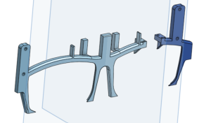

As I said last week it’s in several parts to make it easier to print. I’ve also decided to use some parts of the original casing my display came in, particularly the parts that mount the optical lens and the screen together at the right angle, since trying to replicate its details in an already-complicated print at what would have to be a suboptimal angle would be very prone to printing problems. Like the sidebars, I’ll be able to attach the several front pieces with a combination of the original display casing’s screws and a small amount of epoxy.
I also intended to attach the display to the Raspberry Pis, but when I wired it together by hand I did the I2C for the early tests, it… didn’t work. It lit up with a blank blue screen when I powered it, sure, and I was easily able to get the brightness control lines to work as expected, but when I actually connected the AV data input line to the Rasppi’s AV output while running a very simple test frame generation script, the screen just went dark.
There are several things that could be wrong.
- The Rasppi isn’t outputting the right format.
- Unlikely. I tried with my Rasppi configured for all three major standards, and none of them worked.
- There are three major standards for composite video: NTSC, PAL, and SECOM, with North America generally using NTSC. It’s the default for the Raspberry Pi along with most devices, and the standard I understood this display to use.
- The Rasppi isn’t outputting at all.
- Possible? This device’s configuration is persistently obscure and arcane, so it may be a configuration problem. I used an oscilloscope to detect the waveform on the AV test pads, and it appeared to be what would be expected for a solid black screen. So maybe not just that there’s no signal at all, but maybe:
- The Rasppi isn’t outputting what it should be outputting.
- Also possible. It’s a known but that when using an HDMI peripheral with a Raspberry Pi board, sometimes if the device isn’t attached when the board boots up it just won’t recognize when the attachment occurs. I wasn’t able to find anyone saying this is also true with the AV output, but then, I wasn’t able to find really much discussion of the AV output at all.
- Also a note in this or the previous possibility’s favor: the same behavior occurred when the AV was configured entirely off.
- The Rasppi isn’t outputting in the right resolution.
- Technically possible, but unlikely. NTSC is 720×480, and that’s what the Rasppi generates when configured therefor. The display is nominally 640×480, which I thought was the screen output and not the resolution input, since NTSC is a standard and if you’re going to claim your device takes composite input, it has to take it as a standard. Honestly I don’t even know how I would detect this. Nobody makes tools that output 640×480 composite, because that’s just not a thing. I’ve seen this exact device work with an off-the-shelf HDMI-AV converter, so surely it’s not some obscure custom resolution type. How would you even do that, it’s an analog signal.
- The signal is getting corrupted between the Raspberry Pi and the display.
- Unlikely. I ran ground twisted with the signal on a very short wire in a relatively low-noise environment. A corrupted signal would at least sometimes show me a couple colors that aren’t solid black, I think.
- The display is broken.
- God, I hope not.
I’ve already done some amount of testing to get to the approximate likelihoods as described above, and have more to do early next week when the tools I ordered to help my debugging (RCA AV cable, HDMI-AV converter) arrive. Those tools will also help me build workarounds if the issue cannot be entirely fixed.
I’ve also spent a bunch of hours mostly today and yesterday writing the slides and script for the final presentation.
Progress Schedule
With the completion of the CAD, only a few more steps remain in building the hardware- printing, cutting the mirror and acrylic lenses, and assembly. My machine screws even arrived early. There’s a little bit more testing to be done on the communication between the camera’s Rasppi and the display’s, with the I2C mostly working, but then the on-headset data communication will be complete.
I’m running behind all-around, especially with this AV issue cropping up, but I don’t think it’s irrecoverable yet.
Next Week’s Deliverables
Fixing or finding a workaround for the AV problem is my first priority. Additionally, writing the final paper is going to take a significant amount of time. Then assembly. All of the devices can be hooked up and tested working together before they’re mounted.
Verification & Validation
I accidentally wrote up this week’s additional response last week instead of the intended one (oops), so this week I’m filling out last week’s. I’ll probably come back and switch them when I’m cleaning up my links and such so at least they’ll be in the right place eventually.
Subsystem verification tests:
- I2C communication
- Small messages (a byte, the size of our real messages) sent five times per second over the I2C line to determine how solid the connection is, though it’s known to be somewhat faulty. Four-in-five returned acknowledged, on average, which is more than I had the first time I tried a similar version of this test with another method, but I believe this is more accurate since it uses the real messaging methods that my I2C library provides rather than just i2cdetect, which may have had an artificially low success rate due to timing weirdness in the clocks. I’m not sure. I wasn’t able to replicate the low rate again.
- Messages replicating those that the algorithm run by the camera board will trigger sent manually to the display board, to test its responsiveness.
- The whole on-headset system, with the wrapper on the MediaPipe algorithm sending I2C messages (mediated by a debouncer, so it doesn’t send a ton at once before the user processes the update has occurred and removes their hand) which are received by the image generation script and used to modify the display output.
- This one hasn’t been run yet, but I plan to time it as well using the Rasppis’ real-time clocks to ensure we hit our latency requirement.
- AV communication
- All my problems with this are described above. These are tests I have or will run in an effort to debug it.
- Oscilloscope to make sure there’s output on the pad (as expected for solid black, not what should be in the image buffer).
- Run it with different standards, and with AV entirely disabled (no behavior difference).
- Run it with the AV device already connected before power on (will require additional hands).
- Run the AV output to a known-functional AV device (the TVs in my dorm house take composite, and I’m shortly to get my hands on an RCA cable).
- Run HDMI output to an HDMI->AV converter board, which itself is connected to the display (only maybe necessary- possibly part of a workaround if it’s the Rasppi I absolutely cannot get it to output what I need).
- CAD print
- Test print with some mounting points available. Mostly to see how accurate my printer is at fine details, and make sure my measurements at the margin of error I expected were good. Outcome was positive, despite the poorly designed print triggering a lot of support structures being necessary.
- Recognition algorithm
- Pipe the camera output with the MediaPipe landmarks identified as an overlay to my laptop screen (X-forwarding through my SSH tunnel) to see what it’s doing, make sure it’s doing what I expect.
- Used this to identify the source of the initial extreme fall-behind, before I forced a ceiling on the frame rate (and fixed the camera interpreter settings).
- Run the full recognition algorithm at very low frame rates and raise it slowly until it cannot keep up; i.e., its own reported frame rate drops below the nominal one delivered by the camera. We want to keep it at the edge of functionality but not over, because pushing it too far tends to trigger overclocking (sometimes okay in short doses, very bad on long loops: causes overheating, ultimately slowdown, very high power draw, shortens the lifespan of the processor).
- Pipe the camera output with the MediaPipe landmarks identified as an overlay to my laptop screen (X-forwarding through my SSH tunnel) to see what it’s doing, make sure it’s doing what I expect.
- Display
- Most of the display design was done by Charvi, so she did its verification tests. I set up the HDMI output so she could see the actual images as she went before we had the display attached (mostly before we had the display at all, actually).
- Battery life
- Run the Raspberry Pis with the scripts going on battery power from full charge for at least an hour and a half, make sure it doesn’t die. The power draw from the scripts, based on their design, should be relatively constant between nothing happening and actual use. Additionally, I expect the peripheral devices to draw a marginal amount of power, and this already accounts for power supply/boost board inefficiencies, so an extra half-hour over our spec requirement is certainly enough to ensure that with those extra parts it will still be enough.
- Also, ensure the boards do not rise above comfortable-to-the-touch. Since we’re strongly avoiding overclocking, I do not expect it to.
- Run the Raspberry Pis with the scripts going on battery power from full charge for at least an hour and a half, make sure it doesn’t die. The power draw from the scripts, based on their design, should be relatively constant between nothing happening and actual use. Additionally, I expect the peripheral devices to draw a marginal amount of power, and this already accounts for power supply/boost board inefficiencies, so an extra half-hour over our spec requirement is certainly enough to ensure that with those extra parts it will still be enough.
System validation tests for the headset:
- Run all the devices (including peripherals) for at least an hour, with periodic changes of environment, gesture inputs.
- Time the latency from gesture-input (marked by when the camera registers the first frame with a given gesture) to display-update. This is referenced above from one of my verification tests. The setup in order to take this time will greatly resemble that.
- Use the device for an extended period of actual cooking.
- User comfort-survey; have other people wear the device and walk around with it, then take their rating out of five for a few points (at least comfort and interest in trying real use; probably others as well).
- If the users are interested and willing to give us a more detailed holistic review we may allow them to actually use the device, but since this depends on their short-term available time and resources, we will not be requiring it.