Team Status Report for 4/27

Overall progress:

On the software side, what is left is finishing the software-hardware interface. On the hardware side, we have made the order for the PCB.

Significant risks and risk management:

Risk:  Ensuring the PCB works correctly

Description: When shipping the PCB with PCBWay, we found that it was impossible for the PCB to arrive on time if we wanted it to be fully assembled due to the manufacturer unable to source all the parts. As such, we have to manually reflow parts of the PCB. This is a risk as parts might go wrong during the reflow process.

Severity: If an error happens during the reflow process, our PCB will not work intended. This will likely mean that our final product will only be in simulation.

Resolution: Unfortunately there is not much we can do to prevent this risk. We can only put in as much care as we can when we reflow the PCB.


Software tests

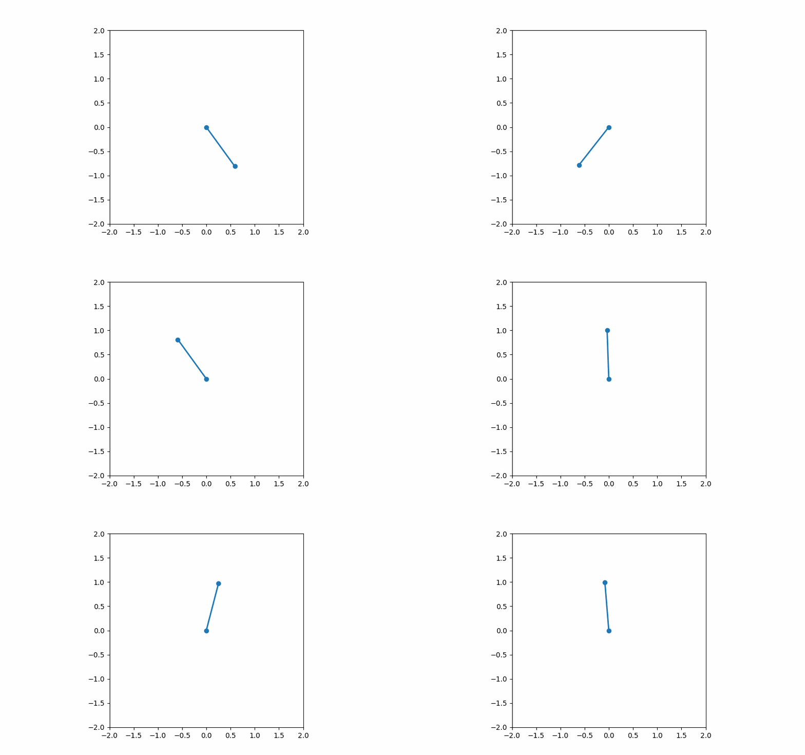
  1. Testing that the SLP solver can swing up the pendulum in multiple starting configurations.
  2. Comparing the solution from the SLP solver with an IPOPT solver to ensure the solution is accurate.
  3. Test the SLP solver with gaussian noise on theta to ensure robustness.
  4. Test the SLP solver with gaussian noise on theta dot to ensure robustness.

Hardware tests

  1. Simulating the hardware with LPs (the first, last, and random LPs) given by the software solver and verifying that results match the software solution.
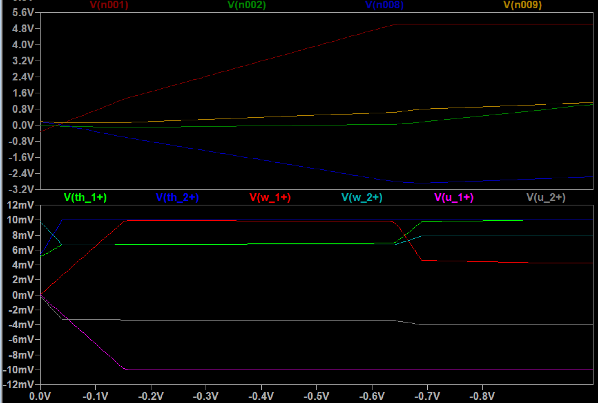
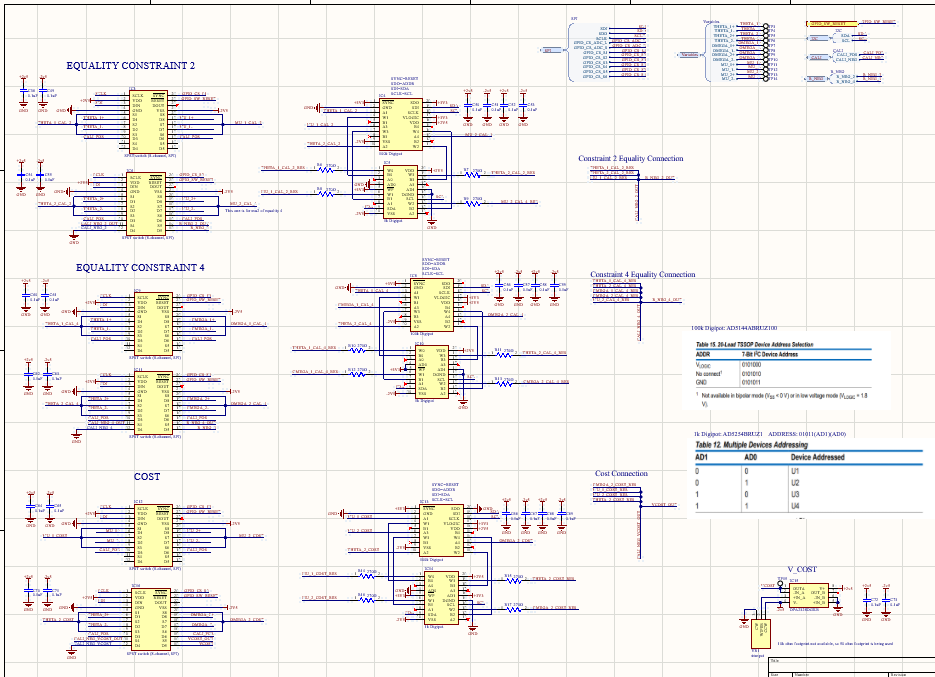
  2. Verifying the circuit behavior matches expectations and ensuring the operation range of the circuit lies within bounds by simulating it.


Changes to the existing design:

There are currently no significant changes to the existing design.

Changes to the project schedule:

There are no significant changes to the schedule as we are nearing the end of the semester.

Thomas’s Status Report for Apr. 27

Personal tasks of this week:

Task: Order PCB and Components

Definition: With Andrew, finalize and order the PCB as well as its components so that they can arrive before demo day.

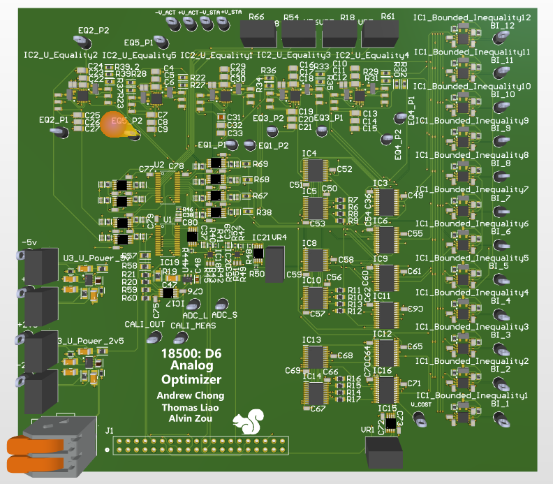
Completion: The task is completed. In the process of ordering, we’ve discovered that it takes PCBWay over 20 days to fully manufacture and assemble the PCB due to the limited availability of some components. Therefore, we decided to order only the PCB from PCBWay, and order the components separately from DigiKey. The PCB will likely arrive on the 30th.

Next Steps:

My next step is to manually reflow the 406 surface-mount components, and solder the through-hole components, once the PCB and the components arrive.

Overall progress assessment:

My progress is behind schedule, because the PCB will arrive a few days before demo, and there are 406 components to reflow. However, we’re hopeful that we can have it fully manufactured by demo day.

Alvin’s Status Report for 4/27

Personal tasks of this week:

Task: Setting up the Raspi-PCB interface

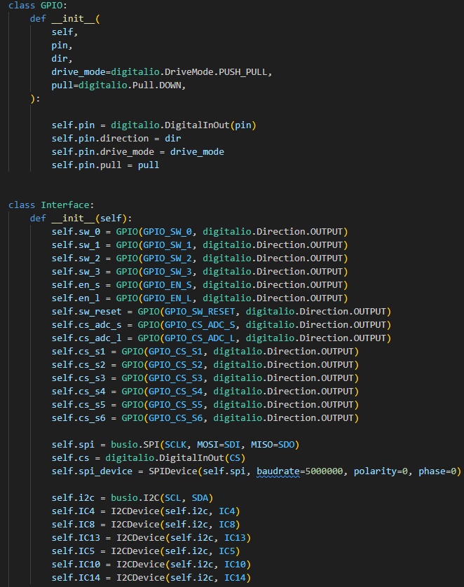
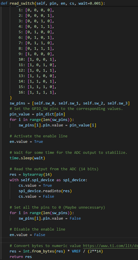
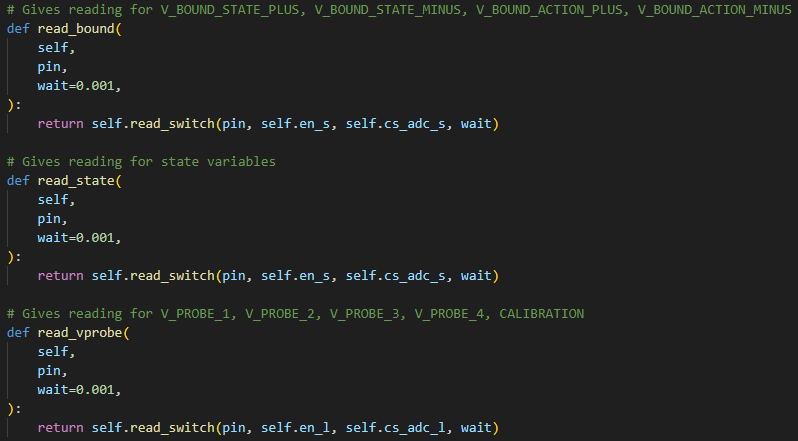
Definition: To communicate between the raspi and the PCB, an interface is needed. Namely, the raspi needs to be able to configure the PCB by controlling switches and digipots on the board, as well as give an input voltage and read an output voltage. Performing these operations will require establishing communication protocols using I2C, SPI, and GPIO.

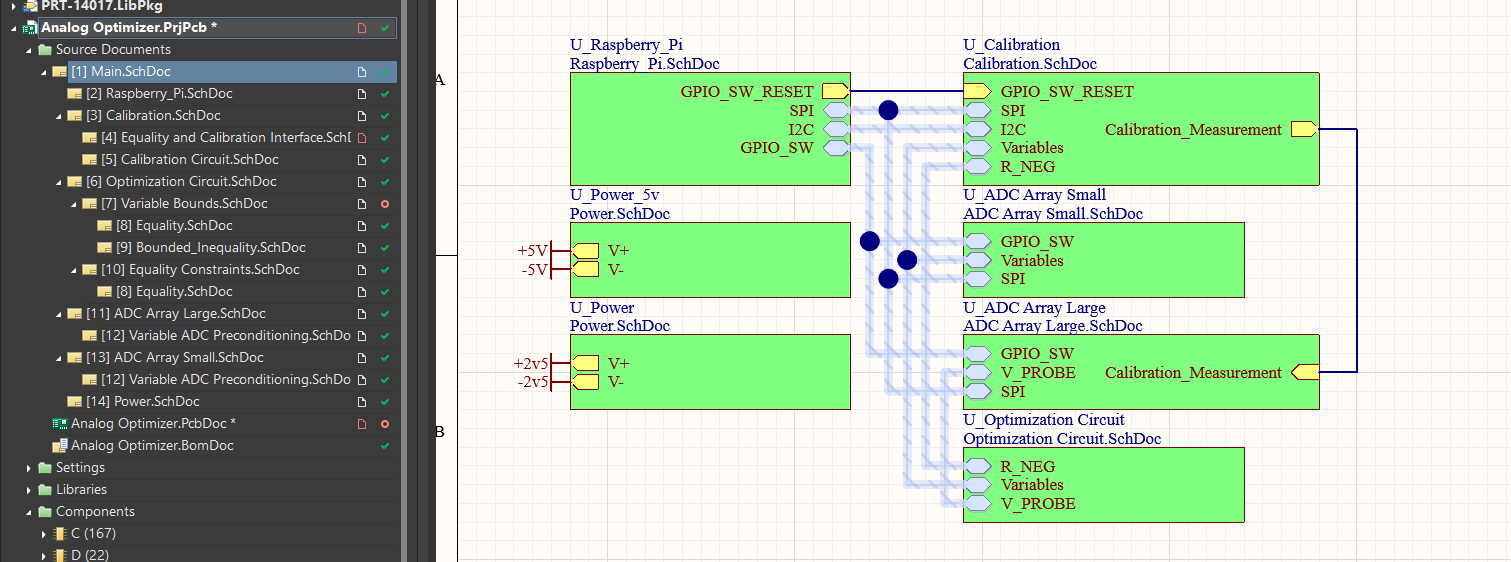
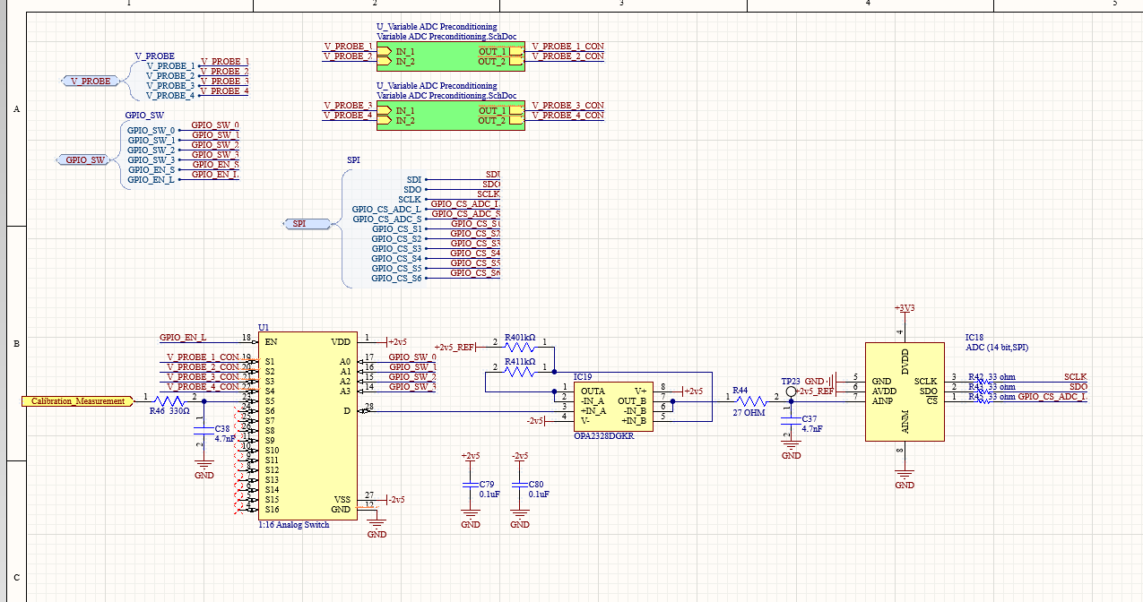
Completion: I was able to verify that the library CircuitPython works for I2C, SPI, and GPIO by testing with the raspi and the arduino. I am now writing the interface between the Raspi and PCB, using our schematic made by Andrew. I currently have the part for controlling the analog switch and reading the ADC completed.

Next Steps:

Create the remaining interface, including controlling the digipots and writing the high level functions that performs circuit calibration, as well as the process of giving the PCB inputs and configuring it, wait for it to converge, then reading the outputs for a LP.

Overall progress assessment:

The remaining work is on finishing the interface and testing the whole system once the PCB arrives. Slightly behind schedule as the PCB is expected to arrive next week, and it is hard to test the correctness of the interface without it.

Andrew’s Status Report for April 20

Personal tasks of this week:

Task: Finalize circuit design and layout

Definition: Finalize the design of the circuit and the layout of the PCB so it can be ordered.

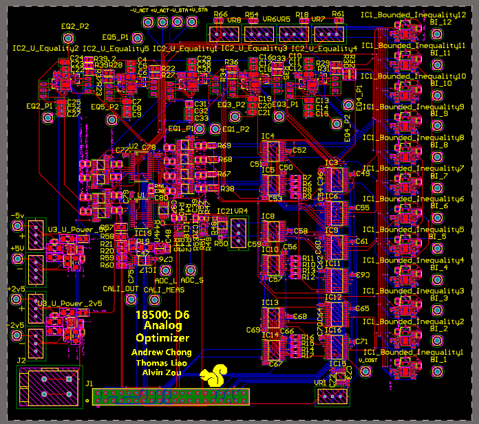
Completion: The task is partially completed. All of the schematics are completed and verified with LTSpice to work. Furthermore, we designed and implemented the digipot calibration method, as well as the protocool we will be using for the pcb. As for layout, there has been some significant progress in figuring out the majority of the connections, but the final layout still needs to be completed.

Next Steps:

My next step is to finish the layout of the PCB

Overall progress assessment:

My progress is somewhat behind schedule, because the PCB is not yet ready to be ordered.

Learning to use new tools:

A new tool I had to learn was LTSpice, which is a circuit simulation software for circuit analysis and simulation. I learned how to use it by looking at tutorials to figure out what was going on and import parts, then figured out the rest from there while looking up specific tools like simulation up.

Thomas’s Status Report for Apr. 20

Personal tasks of this week:

Task: Finalize circuit design and layout

Definition: Finalize the design of the circuit and the selection of all its components. With Andrew, complete the schematic and layout of the PCB in Altium Designer.

Completion: The task is partially completed. We’ve finished the schematics and made significant progress in layout. Many problems in the circuit were identified and resolved, including insufficient tuning accuracy of some trimming potentiometers, as well as OpAmp oscillations due to parasitic capacitances. However, the PCB layout is not yet finished and ready to be ordered.

Next Steps:

My next step is to continue working on the PCB with Andrew. In addition, I will work on digital interface testing with Alvin, so the software running on the Raspberry Pi can interact with the analog circuit  as soon as the PCB is manufactured.

Overall progress assessment:

My progress is somewhat behind schedule, because the PCB is not yet ready to be ordered.

Learning to use new tools:

A new tool I had to learn was LTSpice, which is a circuit simulation software designed for transient as well as frequency-domain circuit analysis. I learned how to use it though reading the official documentation as well as trail and error. Andrew also offered a lot of help since he learned to use LTSpice earlier than I did.

Team Status Report for 4/20

Overall progress:

On the software side, what is left is finishing the software-hardware interface. On the hardware side, we need to finish the layout for the PCB and send it out for shipping.

Significant risks and risk management:

Risk:  Shipping the PCB on time

Description: Figuring out the routing/layout of the PCB is taking longer than expected. This is partially due to the fact that we need to verify the correctness of different parts of the board.

Severity: If we are unable to finish the layout before next Tuesday, we run the risk of not being able to ship the PCB in time.

Resolution: We are currently putting in as much time as possible to finish the layout.

Risk:  While the circuit seems to work properly, we still need to properly identify what kinds of issues arise in the physically circuit

Description: We were able to predict much of the behavior of the “real world” circuit by using the components specified in the BOM. However, the actual behavior of the circuit will obviously be different

Severity: If the inaccuracies of the physical pcb are not properly accounted for, the circuit can have a variety of errors, including non-convergence and solutions with high error.

Resolution: We are currently modeling the behavior of some of these real-world effects as electrical components. For example, we have capacitors on the op amps that do not exist in the theoretical formulation, but exist in the real world analogue due to the parasitic capacitances. However, there are many more places where these issues can occur. The largest source of error compared to the circuit is the transition from resistors to linpots.

Changes to the existing design:

There are currently no significant changes to the existing design.

Changes to the project schedule:

We are trying to put as much time as we can to finish the PCB.

Alvin’s Status Report for 4/20

Personal tasks of this week:

Task: Verifying the SLP solver

Definition: Although the SLP solver seems to be running correctly based on its simulation gif, we still need to verify its correctness by comparing it against other solvers. In addition, it needs to be tested against noise.

Completion: I compared results of the SLP solver with an IPOPT solver, and both gave the same results, verifying that the SLP solver is correct. I also tested the solver with an added gaussian noise to theta, and it was still able to solve the problem, indicating that it is robust to some noise.


The above gif shows the system with added noise.


Task: Setting up the Raspi-PCB interface

Definition: To communicate between the raspi and the PCB, an interface is needed. Namely, the raspi needs to be able to configure the PCB by controlling switches and digipots on the board, as well as give an input voltage and read an output voltage. Performing these operations will require establishing communication protocols using I2C, SPI, and GPIO.

Completion: I was able to find a library that contained drivers for I2C, SPI, and GPIO communication for the raspi. I successfully created an interface for writing from the raspi using SPI.


New Tools/Knowledge Learned:

Throughout this project, I learned a lot about the mathematical theory behind model predictive control, sequential quadratic programming, and sequential linear programming. This was done though searching for articles/papers online, and through discussions with Thomas. I also learned a lot about the Casadi library, and how to use it to formulate mathematical problems and real world simulations.


Next Steps:

Create the remaining interface, including reading using SPI, read/write using I2C and GPIO.


Overall progress assessment:

The remaining work is on finishing the interface and testing the whole system once the PCB arrives. Slightly behind schedule as the PCB has not yet been shipped.

Team Status Report of April 6

Overall progress:

We were able to fix the vast majority of the issues that we ran into implementing Sergey’s solver. Furthermore, we were able to create a full scale simulation of the swingup problem both in SLP simulation and LTSpice circuit simulation. In both cases, we were able to verify that the solutions work.

Significant risks and risk management:

Risk:  While the circuit seems to work properly, we still need to properly identify what kinds of issues arise in the physically circuit

Description: We were able to predict much of the behavior of the “real world” circuit by using the components specified in the BOM. However, the actual behavior of the circuit will obviously be different

Severity: If the inaccuracies of the physical pcb are not properly accounted for, the circuit can have a variety of errors, including non-convergence and solutions with high error.

Resolution: We are currently modeling the behavior of some of these real-world effects as electrical components. For example, we have capacitors on the op amps that do not exist in the theoretical formulation, but exist in the real world analogue due to the parasitic capacitances. However, there are many more places where these issues can occur. The largest source of error compared to the circuit is the transition from resistors to linpots.

Changes to the existing design:

There are currently no significant changes to the existing design. However, depending on the root cause of the inaccuracies, we might change the design to fix it.

Changes to the project schedule:

Similarly, there are currently no significant changes to the project schedule. We aim to order the PCB as early as possible.

Andrew’s Status Report for Apr. 6

Personal tasks of this week:

Task: Resolve issues with circuit simulation and test on swingup problem

Definition: To ensure that the circuit will work on the current swingup problem that we are trying to solve, a full scale simulation of that optimization problem must be created and tested.

Completion: The task is completed.  We were able to create a formulation of the 6 variable swingup problem in terms of the constraints. Thomas was able to create an automated method of calculating the resistances needed for each of the constraints on excel. Using this, we were able to very simply create the full contraints of our circuit. To verify that the solution works, we tried the first, last, and a random middle problem to optimizer. For all of the situations, the majority of the solutions were around 0.5% of the optimal solution, with one variable being around 2.5% of the solution. We also did a voltage sweep on the cost function voltage to verify that the previously identified “sweet spot” was the same for all of the problems.


Next Steps:

Now that the current optimization problem is verified to be correct, the pcb must be created and manufactured as soon as possible.


Verification & Validation:

As the circuit simulation is completed, we can now perform tests to gauge its accuracy on the pcb. Namely, we can run the test suite T3 as we defined in our report.

A manufactured PCB that implements the analog QP solver

We will run the test with three different starting positions to verify the correctness of the solver.

Overall progress assessment:

My progress is on-schedule, as all of my tasks this week have been completed.

Alvin’s Status Report for 4/6

Personal tasks of this week:

Task: Tuning the SLP parameters

Definition: The SLP solver includes multiple tunable parameters, including the bounds for the constraints and the time discretization. The damping coefficient is another variable that is adjustable. Tuning these parameters will effect the performance of the solver.

Completion: Apart from affecting the performance of the solver, these parameters also affect the stability/reliability of the circuit. After testing with different numbers, we found that using the (-0.6, 0.6) as the bounds for the state and (-0.2, 0.2) as the bounds for the control input yielded good results.


Note that the pendulum takes multiple swings back and forth before being swung up due to a cost penalty on the control effort.


Next Steps:

Set up raspi and the drivers for communicating with the PCB.


Verification & Validation:

As the digital SLP solver is completed, we can now perform tests to gauge its robustness. Namely, we can run the test suite T2 as we defined in our report.

Run digital implementation 30 times and verify it solves the problem at least 90% of the time

We will run the test with three different starting positions to verify the correctness of the solver.


Overall progress assessment:

The SLP solver is mostly completed, moving on to configuring the raspi. On schedule.