
- Work this week
- This week I finished our second 3d printed housing. I cut more lenses housings and 3d printed the part to attach to the PCB, and assembled and tested everything. This housing works as well as the first, so mechanical work on the boards is done.
- I discovered that the “low” power setting on one board is pretty high. This seems to be causing some inconsistency in communications, as the receiver cannot always tell it is supposed to be low.
- I worked with Anju and Roger to integrate the whole communication pipeline together. We both ran tests using a mirror to reflect data back to a board and using both boards. Reflecting data back worked well, but using both boards was difficult for some reason. I am continuing to debug why. We did this sending raw bytes, not data encoded in our actual format.
- Schedule
- We are still working on integration. The comms pipeline has been integrated in its entirety, but it appears buggy, so there is still work to be done. Once that is complete, we will move on to testing.
- Deliverables
- Next week, I will fix the laser on one board to have a lower “low” power setting to make communications more reliable. I will also continue work on integration with Anju, and will make a test setup to hold the boards stable for easy testing. I also plan on disabling the IR laser to prevent accidents, since we are not using it at all.
- V&V/Testing
- Have run:
- I have used an oscilloscope to measure the rise and fall times of the signal powering on the lasers to ensure it is sufficiently fast for 6.25 Mbaud communication, which it is.
- We have run a communication test at 6.25 Mbaud through the lasers, with USB and FTDI interface running quite a bit faster, to demonstrate that the hardware can support communication at our required speed. Because we have one laser, not two, this requirement has doubled to 5.42 Mbaud, so we made sure to test above that speed.
- I have done some hand testing with optical angular error. It appears that this error must be significantly smaller than we were hoping for and set as our requirement. I plan to do further work testing this once I have a test stand setup that makes it easier to hold the boards stable, and document more precisely what is required.
- I have measured the current draw of our device and made sure that it draws below the USB-C spec of 3A when powered on 9V USB PD.
- I have tested the board in a variety of lighting conditions (light, dark, different rooms, natural vs artificial) with ambient light filtering on and it consistently performs the same. This verifies that it will work regardless of ambient light conditions.
- Plan to run:
- Measure the received data on digital line to FPGA when receiving 6.25 Mbaud data to ensure it is clean, and rise and fall times meet our spec. Just because it appears to work does not mean this signal is clean.
- Run a test of the full system with the full software stack running and verify speed meets our requirements.
- Run a system stress test transmitting a large file while intermittently blocking the laser and verifying it still gets transmitted.
- Test the boards at a distance of 1m to ensure data can be transmitted at that distance.
- Have run:
Roger Lacson’s Status Report for 4/8/2023
- Personal Accomplishments
- I was able to finish the hamming encoding updates and was able to present these updates at demo day. In terms of structure, Anju and I decided on sending 1024 bytes per packet. Out of these 1024 bytes, 4 are for start bytes, 4 are for the tag ID, and I have now decided to have 1008 bytes to send 693 bytes-worth of data (with the remaining 1024 – 4 -4 – 1008 = 8 bytes of data as padding). The 1008 bytes will consist of 504 2-byte hamming encoded bits. Each 2-byte portion has 11 bits-worth of the raw data that are hamming encoded to 16 bits. I modularized my code, starting with bit manipulation functions (get_ith_bit and set_ith_bit), then the (16,11) hamming encoding function, a function that would take 693 bytes of raw data and hamming encode it into a 1008 byte data packet, and then a function to read a file and then hamming encode all the data. Similarly for the receiver, I added a (16,11) hamming decoder and error corrector/detector, and a full-data decoder.
- I created a test suite for my code. I tested each function individually from the lower-level code (bit manipulation) to the higher-level functions that code/decode entire files. To test the higher-level functions, I encoded files in a directory and decoded them, writing the result to a new file. I use diff to check if the files are equivalent. I then proceed to inject the hamming encoded bytes of files with one-bit errors and decode them to see if the one-bit error correction works properly. I then inject another error which should lead to the file being added into the error queue. I had all this working and verified on demo day.
- I also wrote a simple script to send and receive bytes via laser using the D2XX library for demo day. This code was able to read and write bytes properly on demo day, although the laser itself needed precise alignment to have them work. There is an issue that when there is a read error, the chip does not continue to receive instructions from my laptop, which I need to figure out.
- Schedule
- I am currently still behind schedule according to the original plan, although I should still be able to complete the entire interface code by the end of this week to begin full integration once the board has been properly set and the FPGA is ready. I will aim to finish coding the entire sending and receiving codebase to program the boards to properly send or receive at any given time.
- Deliverables
- Code to properly control the FTDI/FPGA regarding implementing the protocol, sending/receiving data, and coding/decoding data.
- Testing with the hardware and debugging my code/hardware setup based on performance (I do not have many means to test my code other than directly with the hardware).
Anju Ito’s Status Report for 4/8/2023
- Work this week
- Integrated RAM use on the FPGA. Created a 1k FIFO using Quartus IP, and successfully integrated into the code. This fixed the error of not having enough logic components to compile the design on the FPGA, and instead using the embedded RAM on the chip.
- Fixed a FSM logic bug that prevented the FPGA from transmitting 2 bytes in a row over the lasers.
- Fixed timing issue for writes onto the FTDI chip. When testing with lasers, occasionally saw that the 6th bit in the byte was always a one. There was a logic error in the setup time that resulted in data not being held for an appropriate length before the write was asserted.
- Finished writing code and loading all the files for demo. Created a board that can be configured to echo just using the FTDI chip and back, and another that transmits whatever it receives through the USB on the laser and writes back whatever it sees on the receiver back to the USB. Also attempted to test by turning the lasers completely off and on, board-to-board transmission (worked much more poorly then single board using mirrors), and turning ambient light filtering off (not work too well).
- Attempting to fix the board-to-board by creating mounts for the PCB so that they are more stable.
- Working through making the receiver more robust. Cleaned out logic, which may have made it slightly better. However, still occasionally see duplicates in numbers during laser transmission, which needs to be fixed/explained.
- Schedule
- Everything that we prepared for the demo we were able to show, although there are new issues such as the necessity of extremely precise alignments and receivers having errors that need to be addressed in the future. Everything is around 2 weeks behind schedule, as implementation is taking a longer time than planned.
- Next Week
- Attempt to make laser transmission code more robust. Currently seeing duplicates and wrong bits too regularly.
- Potential solutions: Fix any bugs that exist, slow down transmission speed from 6.25MHz, change how the receiver is sampling, add real-life flaws onto simulation to attempt to get error, 3D printed mounts
- Implement handshaking protocol.
- Work with integration and start testing.
- Attempt to make laser transmission code more robust. Currently seeing duplicates and wrong bits too regularly.
- Testing/Verification
- Unit Tests
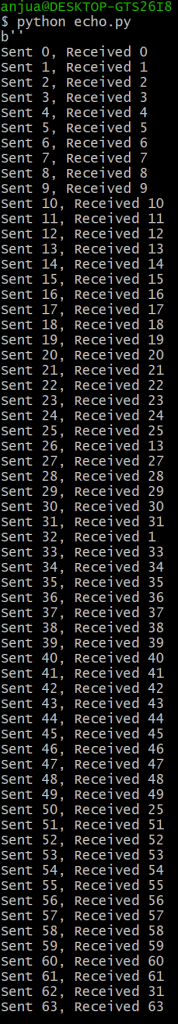
- Echo to test FPGA/FTDI/computer connection: Test that verifies the connection between FPGA to computer by computer writing/reading bytes, and the FPGA echoing that back through the FTDI.
- Verified. Attempted to time, and realized that computer’s read function especially takes a long time to run, but the number of bytes read doesn’t affect speed.
- Laser transmission test: Verifies that the whole pipeline from computer to FPGA to lasers work with single byte.
- Verified. However, alignment changes results a lot, and multiple bytes become less stable.
- Packet send test: NOT DONE. Send a full packet, and verify that it was received correctly on the other side. Should not load it onto the FPGA if the start sequence is not received properly.
- Echo to test FPGA/FTDI/computer connection: Test that verifies the connection between FPGA to computer by computer writing/reading bytes, and the FPGA echoing that back through the FTDI.
- FPGA Integration Tests
- Stress Test: fill FTDI chip multiple times, see if it can process data appropriately
- Speed Test: measure pin out speed with oscilloscope to verify laser transmission
- Light Test: Try testing in different lighting environment to see that transmission works under reasonable room conditions
- Distance Test: slowly move the boards away from each other. Adjust focus, and record the max distance bytes can be transmitted at.
- Unit Tests
Demo
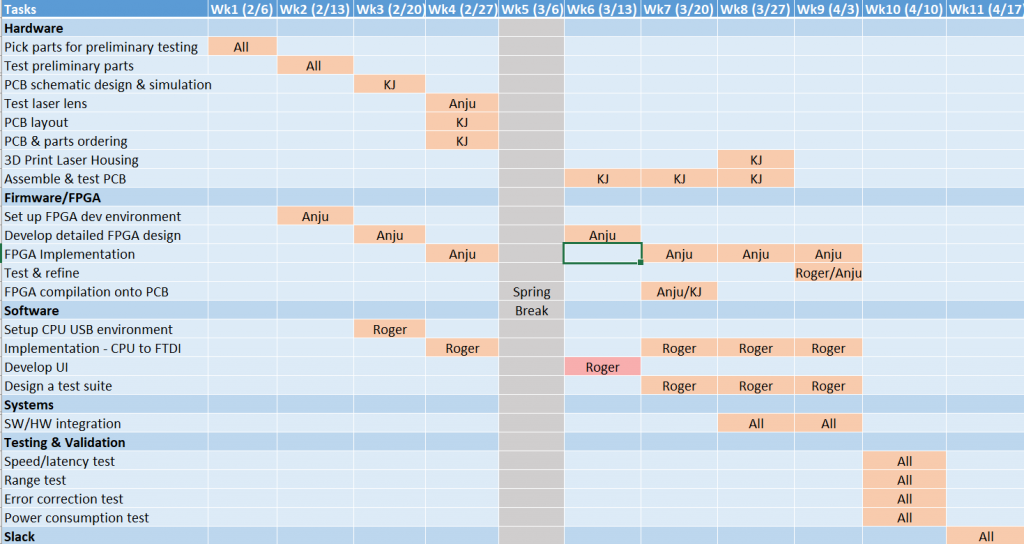
Updated Gantt Chart:
Team Status Report for 4/1/2023
- Risks
- IR seems to use incompatible photodiodes and receivers. We do not have a way to fix this, so we will just not use it. This was always a risk, and a big part of the reason we made sure to have multiple lasers was in case one did not work.
- Design Changes
- We are now using a usb power/data splitter for our usb cable. This allows us to use a usb pd source, like a wall charger, for power, combined with usb 2.0 data from a laptop. The board combines them into one cable for use on our board.
- We are now only using the green laser. IR hardware does not work, but green does. The green also appears potentially fast enough to meet our requirements on its own.
- The charge pumps are creating very large radiated emissions onto our photodiode traces. To deal with this, we are using only the charge pump which is further away from the green photodiode. This is far enough to not introduce noise onto the line. This is done with some resistors attached on top of the board, and the regular charge pump DNP’d.
- Updated Schedule
- We will continue working on integration for the next week and beyond as more subsystems are ready to work together.
- Progress
- The power splitter board came in, was reworked, and successfully delivered both power/data to the PCB. This splits the USB-C line from the PCB into power and data outlet, which can be connected separately to a power supply and a computer.
- The data path from FPGA to laser back to the FPGA was successfully verified at a speed of 6.25 Mbaud, even over just 1 laser!
- The board hardware is seemingly complete!
Roger Lacson’s Status Report for 4/1/2023
- Personal Accomplishments
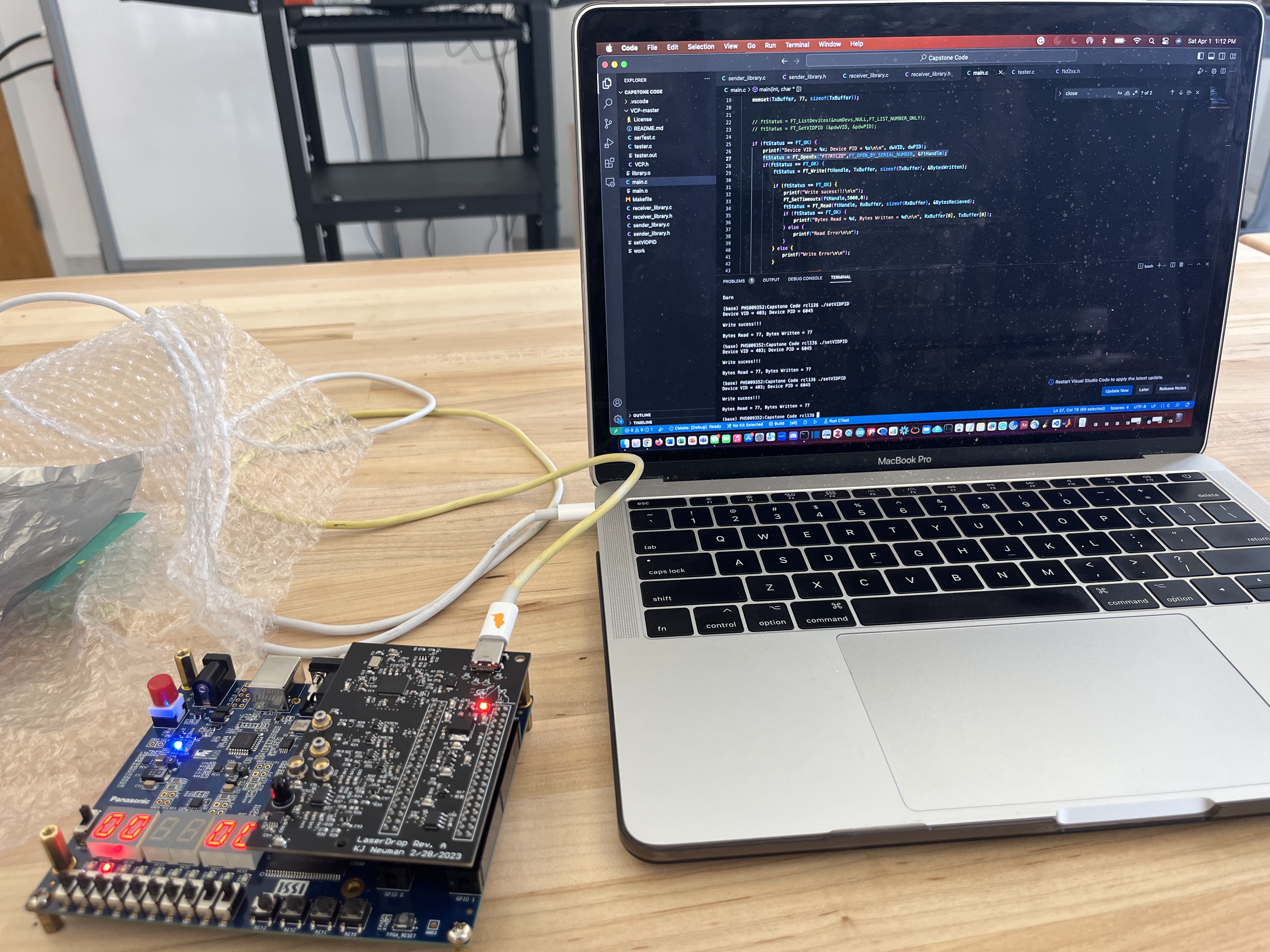
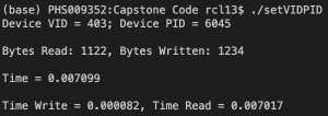
- I was finally able to interface properly with the FTDI chip and FPGA board using an echo program to write bytes to the FPGA. Instead of interfacing through a VCP, we will be using the D2XX library. It seems that read times are slow relative to write times, so this issue needs to be addressed. However, I can now begin to write the full software pipeline for the sender/receiver path. Pictures of the echo and timing are below.
- Anju and I also updated the protocol as the read speeds would slow down the transmission time, and we would like to minimize reads as much as possible. We will return to a previous protocol where all packets will be sent at once, and an error queue will be created with packets that did not pass Hamming decoding and inspection. I will need to implement a priority queue to properly reconstruct packets. Instead of doing these in parallel however, because we will only have one green laser per device, due to the IR laser being rendered unusable, we will not parallelize the processes of the sender sending packets and the receiver requesting errored packets. We will instead wait until all packets are sent, and then re-request all packets from the error queue.
- Additionally, we will increase the tag ID to 4 bytes to avoid the complication we had before of modular arithmetic when packets reached the highest representable byte number (We do not expect a file to be of size 2^42 Bytes or 4.4 TB which would be the size needed to cause tag ID modular arithmetic).
- We will also increase packet sizes to 1 kB (1024 Bytes) to speed up delivery. This will mean that I have to update my Hamming encoding code for an increased number of Hamming bits.
- Schedule
- My schedule is behind now due to all the discoveries and limitations encountered. With that being said, with demo day approaching on Wednesday, I will focus all my attention to write out all this software and test with hardware now that many design choices have been finalized. I don’t expect too many more curveballs, so I can fully commit to the current design ideas. I plan to have a fully functioning Hamming encoding demonstration for Wednesday, and possibly the pipeline to send bytes from one device to another via laser provided that Anju can finish her script for controlling the FPGA.
- Deliverables for Next Week
- Readjust my Hamming encoding code for the different packet design and increased size.
- New test cases
- Begin fully implementing software that integrates library code Iinto sender and receiver- code for the device.
Anju Ito’s Status Report for 4/1/2023
- Work This Week
- Wrote an echo program that reads bytes on the FTDI, and writes them back so it can be tested with computer software. Some bug exists with the reading, but communication has been established and it was seen that correct bytes can actually be read and written from the chip from both directions.
- Continued to debug the FSM. Transitioning over to building smaller modules.
- Attempted to transmit data at 6.25 Mbaud through laser. Sent it over FPGA, and received correctly on the board! Some bugs about reading, but verified that a single bit width can be detected and read.
- Attempted to compile the Echo, and realized that 512 bits couldn’t be declared. Because that was the intended size for packets, realized that this needs to use built-in embedded memory on the FPGA, and created an IP that may be integrated and used instead. This can hold kbytes of memory, which is more than sufficient for our application.
- Schedule
- We were successful in verifying that both sides (lasers and FTDI chip) work to and from the FPGA. Next steps include debugging and building a more robust system, as well as integrating it into the full system. Things are behind schedule, partly as integration requires different projects and modules, which slows progress of FPGA development because they are not as modular as software.
- Next Week
- Figure out a code to put on the FPGA board during the demo
- Make the memory work for the FPGA.
- Fix bug for read write on FTDI.
KJ Newman’s Status Report for 4/1/2023
- Work this week
- This week I debugged several more issues with our PCB. I continued work on the comparator issue. I tested our two new comparators, but they did not work. In fact, they worked worse. I discovered several things. One is that the comparator overdrive ranges are all specced far better than reality. The other is that this was not the actual issue. The real problem is that our charge pumps create a huge amount of noise. They do not create noise on their outputs. However, the radiated emissions from them induces current in the traces to the photodiodes. Because we measure current on order of magnitude of microamps, this noise is far greater than our signal. To fix this, the charge pumps should be far away from receivers, with long traces carrying the reference voltage over. However, this cannot be fixed without a new board spin. In the end, I fixed this by only using only the green photodiode photodiode, and the charge pump for the IR photodiode plus a voltage divider to get the correct reference voltage. The reason for only using green is explained in the next bullet. Because the photodiode only draws microamps, a voltage divider creates a sufficiently stable voltage. Because the charge pump is far away on the board, it does not radiate emissions into the signal line.
- I discovered that our infrared laser will not work. The laser only creates a 1 mV signal when turned on directly in front of the receiver. I figure that the receiver’s datasheet showing the optical wavelength response is likely inaccurate, since it shows a graph of a full spectrum, and it is unlikely the manufacturer was able to actually measure this, and we are using a laser below the peak wavelength of the photodiode. This is not fixable without redesign or buying a large number more parts to find compatible ones. This, combined with the aforementioned charge pump issue, led me to make the call to remove IR. The green laser functions, and we do not have the budget or time to fix IR, since the components are incompatible.
- I found a solution to our USB power problem. I got usb power/data splitters designed for raspberry pis and modified them for our use. They allow us to combine a 9V3A usb pd supply and a usb 2.0 data wire into a single usb C wire. I made 2 of these boards and verified that both power and data work.
- I spend a lot of time finding correct resistor values to change precise settings and thresholds for both boards. The current state is that both use green lasers set to 5 mW, and both green receivers are set to correct thresholds.
- I 3d printed and tested our lens mounts. They fit and the lenses allow us to focus the lasers. Additionally, since I included the threaded metal piece, the mounts allow us to focus and unfocus the lasers on the fly. This was done by using a belt sander to file them down to be small enough to fit on the board over both lasers and with good focus.
- I ran a quick test with Anju to see if the laser and fpga work together. They do! On the first try, we were able to send data at 6.25 Mbaud using the laser and receiver. This bodes well for us, particularly since this was done with me holding a mirror by hand in front of the laser, making for a bad signal.
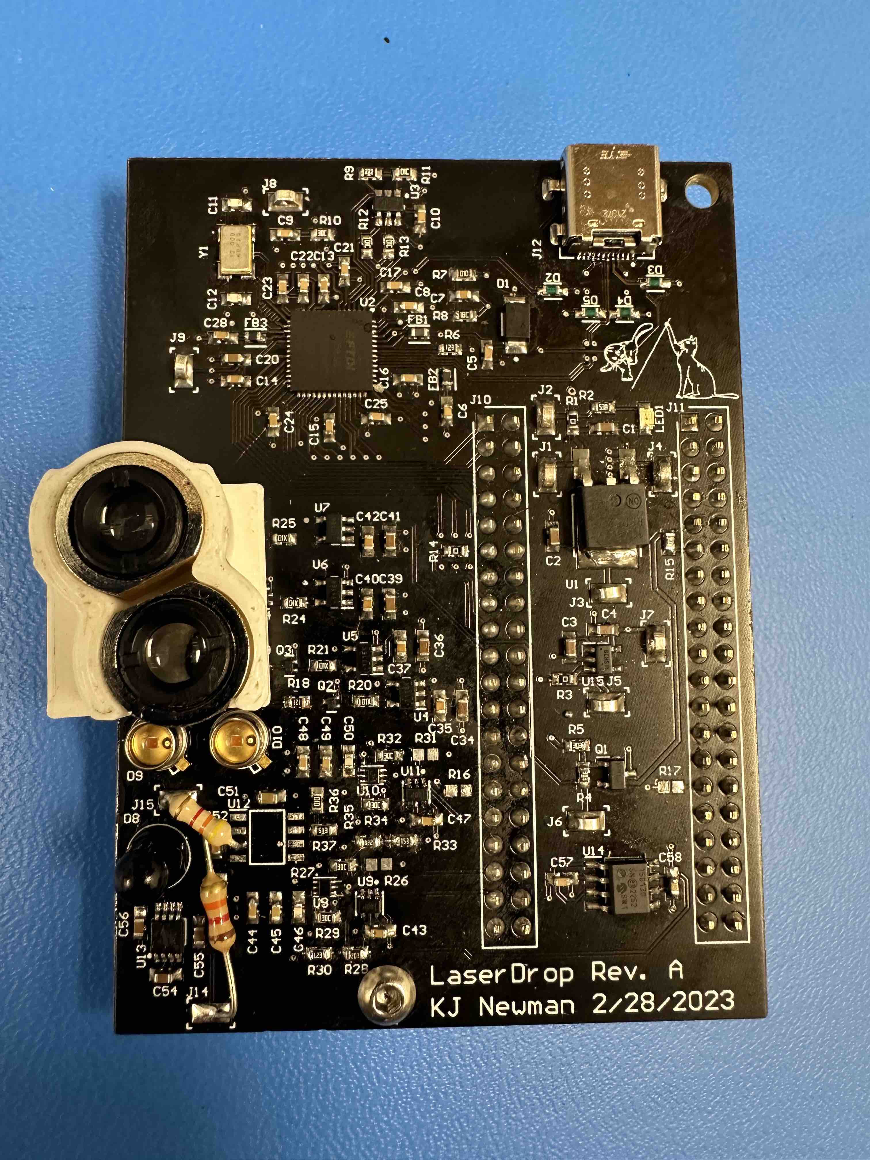
- Image of board now:
- Schedule
- Integration is still behind schedule. Now that hardware seems to be done, this is my number one priority. Since the preliminary test with Anju worked well, and Roger is able to communicate over USB, this seems mostly done. However, we cannot be sure bugs do not remain.
- Deliverables
- Next week, I will finish our second 3d printed housing test. I finished the housing, but I have not assembled and tested it. I also need to use the belt sander to cut the metal pieces down to size.
Roger Lacson’s Status Report for 3/25/2023
What I did
I worked with Anju and contacts in ECE who have more experience with embedded systems in an attempt to program the EEPROM to control the power draw and VCP and FIFO modality of the FTDI chip. I had difficulties understanding the data sheet and relied heavily on my friends and Anju. Anju and KJ were ultimately able to program the EEPROM settings for power draw.
I wrote test cases for my hamming encoding code and have debugged various portions of my code.
I have begun thinking about implementing a script that takes in user input to start detecting, sending, or otherwise waiting idly. I have a simple main function that takes in a 0 or 1 for now to indicate send or receive. I hope to develop a more sophisticated system for setting modality.
Schedule
My Schedule was slightly delayed by my inability to understand interfacing with the hardware. I hope to test further this week to understand how to send signals to the device and have code for next week. I hope to work heavily this week attempting testing USB C communication to make up for my delay.
Deliverables
I hope to have a rough working system that interfaces with the PCB to flash lasers upon signaling and receive laser signals upon signaling. At the very least, I hope to understand the pipeline for signaling between my computer and the device.
Anju Ito’s Status Report for 3/25/2023
- Work This Week
- Designed, programmed, and compiled the FPGA FSM and datapath, though it needs much debugging work.
- Got the simulation to run and wrote a testbench. The testbench did not work for a while due to syntax issues with ternary operations, but runs now and there are issues to debug.
- Helped look at EEPROM programming to set the chip to 245 asynchronous FIFO mode using 9V 3A power delivery.
- Schedule
- The code is slightly behind schedule, and I hope to finish debugging the FSM through simulation by this week so that integration goes smoothly by the end of this week or next week.
- By the interim demo, I hope to have a working FPGA code written. Although this cannot be demoed unless an FTDI chip and computer software is written. The basic sending data and receiving may be demonstrated as MVP.
- Next Week
- Finish debugging the full FPGA code through simulation.
- Help out in other tasks as necessary, and possibly integrate with code/FTDI chip/lasers.