- Work this week
- This week I worked on debugging the usb driver. I located a document which specifies what the error codes that ftdi functions return mean. I then added a lot of debugging code to print these codes in human readable form anytime there is any error. It seems that some fpga code changes have mostly gotten rid of errors while operating. However, setting baud rates above 7 Mbps still has issues. I printed the error code when this happens, and it is FT_IO_ERROR, which is ill documented. I believe that some baud rates cannot be achieved with the clock dividers on the chip. However, these are not documented anywhere. Therefore, we are likely to stick to 7 Mbps.
- I worked on our poster this week. Anju had already started the poster but it was difficult to edit, so I made a new copy and copied all information over. I also spent a while trying to make sure the text in images would not need to be rescaled because that was making it blurry and poor quality. The poster is pretty much done now. As a team, we will look at it together.
- Schedule
- We are on schedule. I only have work on the report, poster, and video remaining. We also need to do the system stress test.
- Deliverables
- Next week, I will be finishing up on the poster and working on the report. I will also run the full system stress test.
Team Status Report for 4/22/2023
- Risks
- We discovered that when sending a large number of 1’s in a row, ambient light filtering kicks in and starts flipping them to be 0s. This means that we cannot send most files. To mitigate this risk, we have two proposed design changes as described in the next section. Both ideas seem to pass preliminary testing.
- The USB driver crashes when reading occasionally. This happens frequently enough to prevent us from transmitting large files. We are not sure why this happens yet. We plan to look into this bug and hopefully find what is happening. If we do not figure it out, we will try to have the code try to reload the USB Device repeatedly if it happens.
- The software sometimes goes into a deadlock when both receiver and transmitter has data on its TX buffer. The timing and acknowledgements is hard to get right, but we may make some assumptions to make this work.
- Design Changes
- Because of the series of 1’s bug that changes the threshold for the ambient light, we need to change our design. The two options are to turn off ambient light filtering or change data encoding on FPGA. We have demonstrated that both ideas work through testing, although the system still sometimes crashes with ambient light filtering off. With the new encoding on the FPGA (keeping light filtering on), it works extremely well with no errors/crashes. The current plan is to use that for our final design.
- Each packet will have a handshaking before starting transmission. This design change was made to avoid the computer needing to resend the packet as much as possible, since the computer to FPGA speed seems to be the bottleneck for our project.
- The error queue/acknowledge is sent from the receiver every 128 packets. This was originally after every packet, but through the use of software drivers we found the read operation to be extremely slow compared to everything else, which led to this change.
- We will either use 4.17 Mbps or 6.25 Mbps speed for our transmission, which we found to work through testing. Originally, this was planned to be slower.
- We will be using a 11-16 bit Hamming encoding instead of the whole packet. We found that bit-flips are common within a byte, so this would ensure that more can be caught, even though it will eat in to the amount of usable data sent. In addition, the packet size got much bigger than the original 64 bytes planned.
- Updated Schedule
- Our integration and debugging has slid behind schedule, and we are cutting into slack. However, we managed to get the whole system integrated and mostly working. We also performed multiple tests, and the tasks left are refining, making design trade-offs, and documentation. We will continue work on debugging while preparing for our final report and demo.
- Progress
- We sent complete files through the whole protocol! Everything works at least somewhat, and we are now onto debugging rather than implementation. We have sent a file as large as 19 MB without any issues.
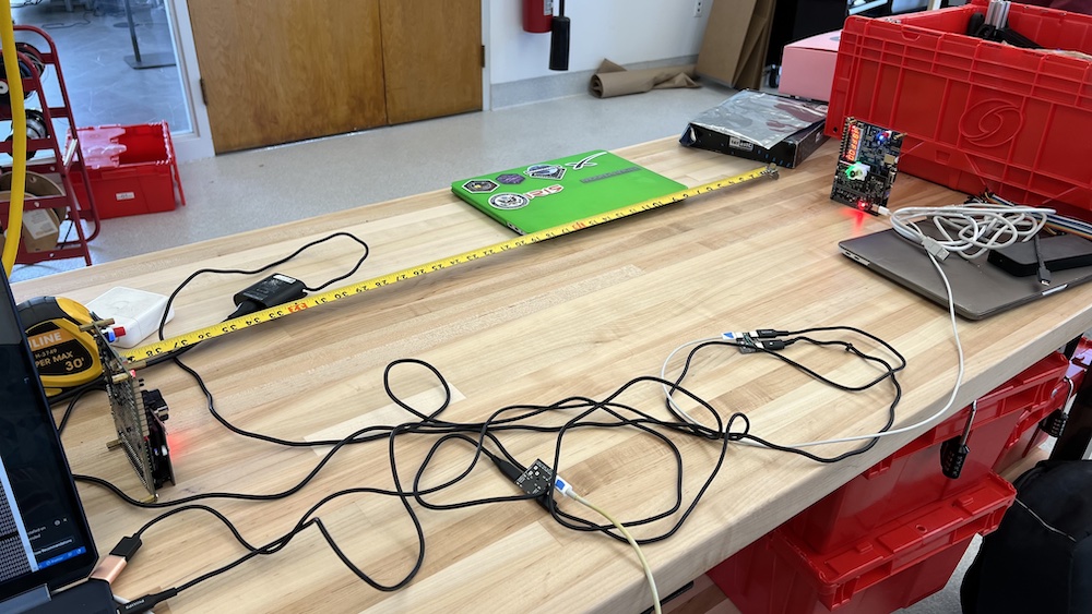
- Performed various tests (distance, lightings, different speeds, timing each)
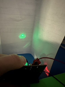
![]()
Transmission of Image from one computer to another!
KJ Newman’s Status Report for 4/22/2023
- Work this week
- This week I spent a lot of time working on software. The code was not complete for integration, so I both debugged and added features to get it to the point where it could be tested along with the rest of the project. This included splitting up and reconstructing files, fixing the way boards are identified to use individual names (Black and White, to match their 3d printed parts), increasing usb speed, and much more. The software is now in a state where it works and it can deal with packets with errors, but if there are errors in protocol packets that do not contain any file data, it sometimes fails.
- I worked on integration a lot this week. Early in the week, I fully integrated hardware and FPGA firmware with Anju, and demonstrated transmitting data at various speeds at various distances between two boards. This fulfilled our testing for hardware for the most part, and it worked very fast!
- During integration, I discovered that when a large number of 1’s are send consecutively, the ambient light filtering loop kicks in and thinks it is ambient light, since the parts we use are designed for laser rangefinders, not communications. To fix this for now, we have disabled ambient light filtering, and the system works. However, we are testing a new way of encoding data where the first half of a bit is data and the second half is 0 to prevent this from happening. This may allow us to keep the light filtering on. I have found experimentally that ambient light filtering is not necessary in most cases, since the board is not facing high intensity green light. Based on preliminary testing, this approach works very well! It limits our speed to 4.167 Mbaud over lasers, but it has zero errors!
- I finished our slides this week, which includes having data for most of our tests, and a video demonstrating that we can send files!
- Schedule
- We are still working on integration. The whole system is now together, and we are working on debugging issues for the next week or two until the demo.
- Deliverables
- Next week, I will continue working on integration and fixing issues. I will work with Anju to finally select whether we will turn off ambient light filtering or change data encoding to allow filtering to stay. I will also work with Roger on debugging the usb driver, since it fails when reading sometimes, preventing us from transmitting large files.
Team Status Report for 4/8/2023
- Risks
- Communication between boards seems a lot more unstable than reflecting back to a single board. It is not clear why, but this may be due to aiming the laser needing to be very precise. We may need to reduce our requirement of aiming accuracy needed for the lasers to work.
- The receiver on the FPGA were encountering issues when tested by itself, which may be due to not using the PCB board. Currently, we are seeing duplicates, and the FPGA code may still have concurrency bugs that can be fixed to make receiving more accurate.
- Design Changes
- We realized it is pointless to include 2 lenses if we are only using one laser, so now each lens housing only holds a lens above the IR laser.
- The header sequence for each packet will now be 4 bytes instead of 1 for increased reliability.
- The packets will now be sent continuously (not waiting for a feedback) from the transmitter, and the receiver at the end will send back all the tags that are missed at the very end so that they can be resent.
- The tag ID byte length was changed from 1 to 4 bytes, so that we will never encounter a wrap around, making software easier to implement with relatively low cost in terms of packet size.
- The packet size will increase from the originally planned 64 bytes into kbytes. This decision was made because we figured out that the FPGA embedded memory that allows us to store that many bytes, and the C read/write functions were slower than expected, so batch operations can help lower the time needed per byte.
- Updated Schedule
- We will continue working on integration for the next week and beyond as more subsystems are ready to work together.
- Progress
- We sent data from one laptop to another through the laser! This was raw data, but it was a very big step to demonstrate that the entire pipeline works.
- We completed the second lens and lens holder assembly, so now both boards have complete mechanical setups.
KJ Newman’s Status Report for 4/8/2023
- Work this week
- This week I finished our second 3d printed housing. I cut more lenses housings and 3d printed the part to attach to the PCB, and assembled and tested everything. This housing works as well as the first, so mechanical work on the boards is done.
- I discovered that the “low” power setting on one board is pretty high. This seems to be causing some inconsistency in communications, as the receiver cannot always tell it is supposed to be low.
- I worked with Anju and Roger to integrate the whole communication pipeline together. We both ran tests using a mirror to reflect data back to a board and using both boards. Reflecting data back worked well, but using both boards was difficult for some reason. I am continuing to debug why. We did this sending raw bytes, not data encoded in our actual format.
- Schedule
- We are still working on integration. The comms pipeline has been integrated in its entirety, but it appears buggy, so there is still work to be done. Once that is complete, we will move on to testing.
- Deliverables
- Next week, I will fix the laser on one board to have a lower “low” power setting to make communications more reliable. I will also continue work on integration with Anju, and will make a test setup to hold the boards stable for easy testing. I also plan on disabling the IR laser to prevent accidents, since we are not using it at all.
- V&V/Testing
- Have run:
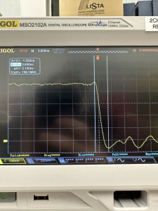
- I have used an oscilloscope to measure the rise and fall times of the signal powering on the lasers to ensure it is sufficiently fast for 6.25 Mbaud communication, which it is.
- We have run a communication test at 6.25 Mbaud through the lasers, with USB and FTDI interface running quite a bit faster, to demonstrate that the hardware can support communication at our required speed. Because we have one laser, not two, this requirement has doubled to 5.42 Mbaud, so we made sure to test above that speed.
- I have done some hand testing with optical angular error. It appears that this error must be significantly smaller than we were hoping for and set as our requirement. I plan to do further work testing this once I have a test stand setup that makes it easier to hold the boards stable, and document more precisely what is required.
- I have measured the current draw of our device and made sure that it draws below the USB-C spec of 3A when powered on 9V USB PD.
- I have tested the board in a variety of lighting conditions (light, dark, different rooms, natural vs artificial) with ambient light filtering on and it consistently performs the same. This verifies that it will work regardless of ambient light conditions.
- Plan to run:
- Measure the received data on digital line to FPGA when receiving 6.25 Mbaud data to ensure it is clean, and rise and fall times meet our spec. Just because it appears to work does not mean this signal is clean.
- Run a test of the full system with the full software stack running and verify speed meets our requirements.
- Run a system stress test transmitting a large file while intermittently blocking the laser and verifying it still gets transmitted.
- Test the boards at a distance of 1m to ensure data can be transmitted at that distance.
- Have run:
KJ Newman’s Status Report for 4/1/2023
- Work this week
- This week I debugged several more issues with our PCB. I continued work on the comparator issue. I tested our two new comparators, but they did not work. In fact, they worked worse. I discovered several things. One is that the comparator overdrive ranges are all specced far better than reality. The other is that this was not the actual issue. The real problem is that our charge pumps create a huge amount of noise. They do not create noise on their outputs. However, the radiated emissions from them induces current in the traces to the photodiodes. Because we measure current on order of magnitude of microamps, this noise is far greater than our signal. To fix this, the charge pumps should be far away from receivers, with long traces carrying the reference voltage over. However, this cannot be fixed without a new board spin. In the end, I fixed this by only using only the green photodiode photodiode, and the charge pump for the IR photodiode plus a voltage divider to get the correct reference voltage. The reason for only using green is explained in the next bullet. Because the photodiode only draws microamps, a voltage divider creates a sufficiently stable voltage. Because the charge pump is far away on the board, it does not radiate emissions into the signal line.
- I discovered that our infrared laser will not work. The laser only creates a 1 mV signal when turned on directly in front of the receiver. I figure that the receiver’s datasheet showing the optical wavelength response is likely inaccurate, since it shows a graph of a full spectrum, and it is unlikely the manufacturer was able to actually measure this, and we are using a laser below the peak wavelength of the photodiode. This is not fixable without redesign or buying a large number more parts to find compatible ones. This, combined with the aforementioned charge pump issue, led me to make the call to remove IR. The green laser functions, and we do not have the budget or time to fix IR, since the components are incompatible.
- I found a solution to our USB power problem. I got usb power/data splitters designed for raspberry pis and modified them for our use. They allow us to combine a 9V3A usb pd supply and a usb 2.0 data wire into a single usb C wire. I made 2 of these boards and verified that both power and data work.
- I spend a lot of time finding correct resistor values to change precise settings and thresholds for both boards. The current state is that both use green lasers set to 5 mW, and both green receivers are set to correct thresholds.
- I 3d printed and tested our lens mounts. They fit and the lenses allow us to focus the lasers. Additionally, since I included the threaded metal piece, the mounts allow us to focus and unfocus the lasers on the fly. This was done by using a belt sander to file them down to be small enough to fit on the board over both lasers and with good focus.
- I ran a quick test with Anju to see if the laser and fpga work together. They do! On the first try, we were able to send data at 6.25 Mbaud using the laser and receiver. This bodes well for us, particularly since this was done with me holding a mirror by hand in front of the laser, making for a bad signal.
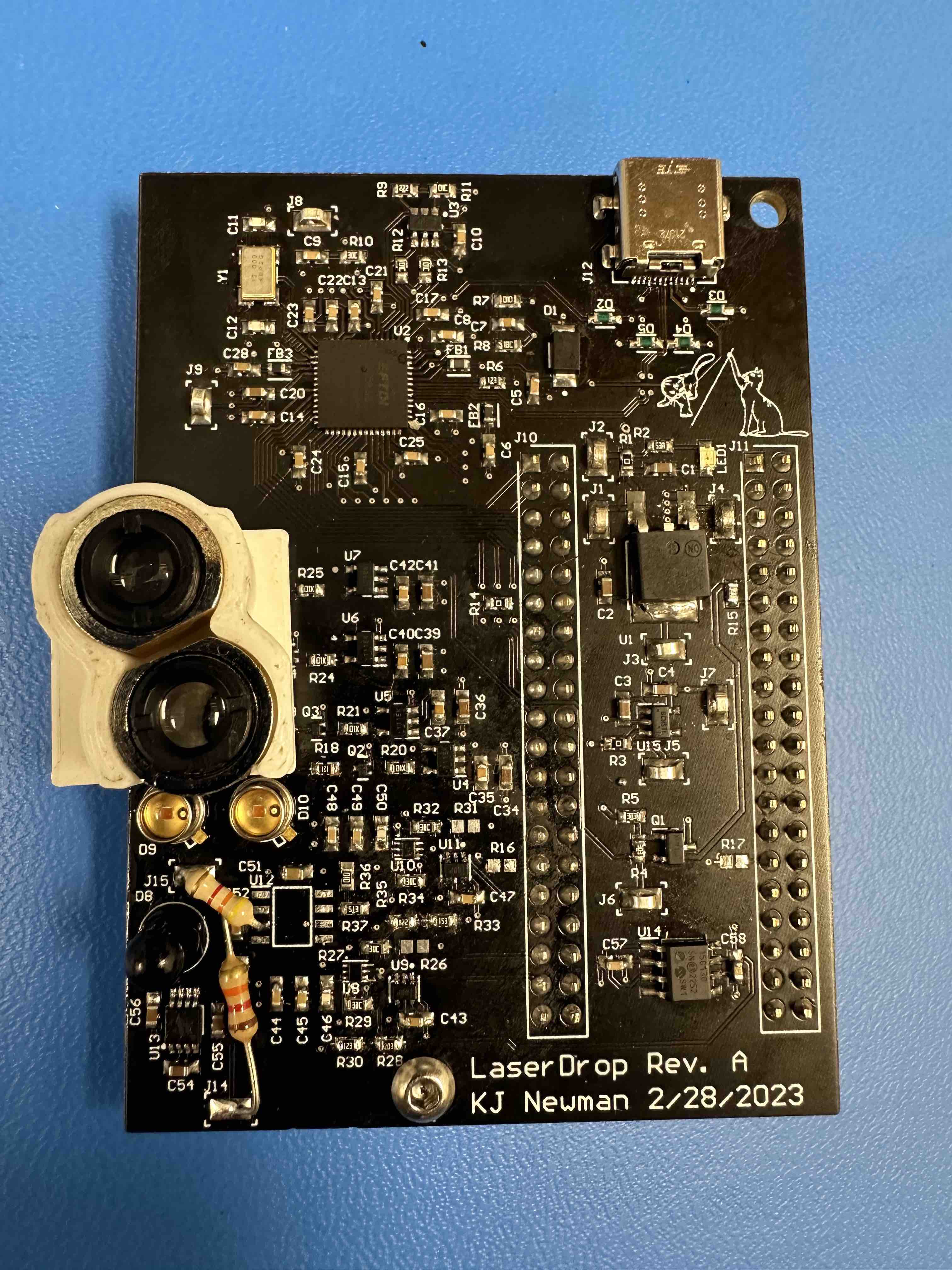
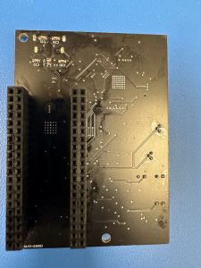
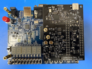
- Image of board now:
- Schedule
- Integration is still behind schedule. Now that hardware seems to be done, this is my number one priority. Since the preliminary test with Anju worked well, and Roger is able to communicate over USB, this seems mostly done. However, we cannot be sure bugs do not remain.
- Deliverables
- Next week, I will finish our second 3d printed housing test. I finished the housing, but I have not assembled and tested it. I also need to use the belt sander to cut the metal pieces down to size.
Team Status Report for 3/25/2023
- Risks
- This week we fixed several risks, including low laser power and the FTDI power chip not working. However, we also added several more:
- One is that Macs do not support our usb power plan. We need to find a new power solution. We plan on researching available usb splitters and powered usb hubs that may fit our needs. Worst case, we can either hand splice a wire to separate power and data or we can use a power supply separate from USB. However, we plan on looking into better alternatives than that.
- Another risk is that the comparators do not work. Our original comparators for our receivers do not work as well as the datasheet suggests, and therefore our circuit does not create enough overdrive voltage for them to have digital outputs. To mitigate this, we purchased 2 different new comparator chip models that should perform better. They are the same footprint and will work perfectly if the datasheets are correct. If they both end up not working, we can wire in a breadboard with more analog circuits to fix this. However, that would greatly limit our max communication speed, so we are trying new comparators first.
- Simulation on the FPGA had difficulties running due to subtle syntax differences. The biggest of these were debugged, but the ability to easily verify it might be time-consuming in the future.
- Design Changes
- We will need some new part to fix our usb power delivery issue. This is not yet determined, but will likely be something between our board and the laptop.
- We changed how we will be 3d printing the lens housing. Rather than 3d printing threads or a hole for self tapping, we will cut the metal housing we have down to a small size since it has threads that fit our lens already. Then, we just need to 3d print a circular hole for the housing to sit in, which requires much less precise work.
- We plan on removing the sequence tag ID, once we verify that all of the packets can be performed in-time synchronously. This will be dependent on the speed that the computer can read data off the FTDI, verify the Hamming code, and send data back.
- Updated Schedule
- The actual 3d print and assembly of our lens housing has been pushed to next week due to issues with the board that came up this week.
- Board testing continues to be extended as we encounter unexpected issues with the boards.
- FPGA testing will continue on next week, waiting for software and hardware to work before integration.
- Progress
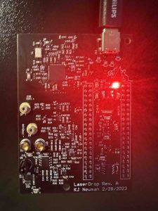
- The board powered over 9V USB PD by configuring the EEPROM connected to the FTDI chip:
- Currently debugging, but a full FSM and datapath for the FPGA was designed and programmed.
- Higher power laser output was produced that can be read better by receivers.
- The board powered over 9V USB PD by configuring the EEPROM connected to the FTDI chip:
KJ Newman’s Status Report for 3/25/2023
- Work this week
- This week I debugged several issues with our PCB. One of these is that the receivers do not work. This is because our comparators are not behaving as specced. They are specified as low as 20 mV overdrive with no minimum spec, but we experimentally found that they only work starting at 50 mV overdrive. Our TIAs do not create a large enough voltage swing for this, so they do not output digital values. To fix this, I ordered 2 new comparators that have several specs well below this, as low as 5 mV overdrive. They still do not have a minimum spec but appear to be better. I also made sure to get chips from different manufacturers in case this is a manufacturer issue. These will arrive next week for testing.
- Another board issue detected this week was laser power. The lasers have visibly inconsistent power output, mostly weaker than expected. I did some experiments and determined that this is because the threshold voltage of our laser diodes is not consistent. To fix this, I connected lasers to external power and used experimental and datasheet values combined to calculate the feedback current that equals our expected optical powers, 2.5 mW and 0.5 mW. I then tested how much input current would create that feedback current for individual lasers. I did this for both lasers on one board and replaced the resistors to equal this power, which makes the board now have the correct power. I now know each laser needs this calibration individually, so will need to do it on the other board too.
- Another issue detected this week was power related. I managed to program the FTDI chip on one board to the correct communication and power settings, but I discovered that the board only successfully draws 9V from a laptop charger, not from my laptop. This is despite Apple customer support explicitly stating that this would work. It seems Macs do not support being a USB PD source above 5V. To fix this, we will need to splice wires or find some device capable of high voltage USB PD and data combined.
- I also received new USB connectors this week, and attached one to our second board. This was much faster and easier than the first, since I had to figure out a method the first time. This time, it worked on the first try with no damage to anything.
- I tested various methods to see what the best way to test a single board is, since we need both a transmitter and receiver to test anything. The best method I found was using a small reflective piece of metal to reflect the unfocused laser back towards the receiver on the same board. This is strong enough to trigger the photodiode and TIA, so this is how I have been testing the receiver.
- Schedule
- Due to the specified board issues, I did not 3d print our lens housing this week. This will be pushed once again to next week. I have made a plan for exactly what shape needs to be made, but do not have CAD for it yet.
- Deliverables
- Next week, I plan to deliver at least one housing for the lens. However, the important deliverables are fixing the circuits. I plan to have fixed the laser power on the second board and have fixed the receivers to properly output digital signals using one of the new comparators. Additionally, I want to have settled on a solution for the USB power, even if it is not implemented yet.
Team Status Report for 3/18/2023
- Risks
- The IR receiver on one board appears to be floating. This is not a huge risk because it is likely a poorly soldered part, but there is a risk that there is something big wrong. We will be looking into this next week to determine exactly what is wrong.
- We tried to do a quick test of the receiver, which did not work. This is most likely due to poor setup, but it may require figuring out how the ambient light filtering works, and how best to aim the boards to each other in order to test accurately, which may take some time and work.
- Design Changes
- Our USB connector did not fit properly on our board, so we needed to bend pins and not attach all pins in order to get it connected. This ultimately resulted in some power and ground pins not being connected as planned. This is not expected to cause any issues but does mean that our board supports less current going through the connector now.
- When writing the FPGA program, we’re slightly split on whether to make it so that both lasers must receive at the same time and transmit at the same time. If we do this, it would add integrity because there is a much smaller likelihood that both would turn on accidentally at the same time, and make handling the protocol easier. However, it would also make it so that testing is difficult. Right now, the decision is that it will only handle simultaneous receiving/transmission, and the code will be modified slightly so that testing can be done with just one.
- Updated Schedule
- We did not do any 3d printing this week due to the assembly process taking longer than expected. This will now happen next week.
- The implementation of the FPGA got slightly overlapped with board integration, and some of the code development would be shifted to testing using the actual PCB.
- Progress
- Boards complete!
- FPGA code written and tested for the laser and receiver module. The FSM that handles the actual protocol behavior is written on the receiver side, but not yet tested.
- FPGA and board integrated, and ensured that GPIO pins control the appropriate circuitry.
- Boards complete!
KJ Newman’s Status Report for 3/18/2023
- Work this week
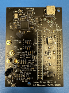
- This week, I assembled two of our PCBs. We did not receive a stencil from JLCPCB, so this took quite a while. The boards assembled as expected with only one exception, the USB connector. The connector requires a board cutout underneath it and the board does not have one, so it took a lot of time to get the connector to fit. Ultimately, I figured out a way to bend the pins and use hot air soldering to get the connector on, but destroyed our 2 other connectors in the process. However, it did work on one board, so we ordered some more connectors to put on the second PCB using the same process. This ultimately will not slow us down much or cost much. The board is shown here:
- I also tested the PCBs. The transmission and power circuits work as expected, and the receiver circuits are difficult to test without FPGA software, so I began working with Anju on integrating the FPGA board and the custom board. Transmitting works integrated with the FPGA, and receiving testing is ongoing. All voltages on the board are correct, and laser driving at two different power levels works with sufficient rise and fall time to transmit at our speeds as shown:
- I verified how the lenses fit over our board and that they properly focus both lasers. I also found that iPhone cameras can indeed see our IR laser, but not very well
- I ordered some additional parts this week. I ordered and received 3d printer filament. I also ordered new usb connectors as we ran out.
- This week, I assembled two of our PCBs. We did not receive a stencil from JLCPCB, so this took quite a while. The boards assembled as expected with only one exception, the USB connector. The connector requires a board cutout underneath it and the board does not have one, so it took a lot of time to get the connector to fit. Ultimately, I figured out a way to bend the pins and use hot air soldering to get the connector on, but destroyed our 2 other connectors in the process. However, it did work on one board, so we ordered some more connectors to put on the second PCB using the same process. This ultimately will not slow us down much or cost much. The board is shown here:
- Schedule
- My work is mostly on schedule. I managed to assemble and test pcbs despite not having the stencil. However, this meant that 3d printing our housing fell behind schedule, and I now plan on doing this next week.
- Deliverables
- For next week, I plan to design our 3d printed housing for the lenses and print it. I also plan on continuing integration of the receiver with Anju and giving a board to Roger for him to integrate USB code and EEPROM settings onto.