- Risks
- One risk is that the PCB will not be capable of the speeds we want. We do not have tremendous experience with high speed routing, so it is possible that the layout will cause issues.
- We will mitigate this by doing a lot of research into high speed routing before doing layout work. Additionally, we will keep high speed traces very short.
- Component availability between early stage of design and component ordering
- We plan on ordering components as soon as schematic work is done to mitigate this. Additionally, we are ordering some extremely low availability components already.
- One risk is that the PCB will not be capable of the speeds we want. We do not have tremendous experience with high speed routing, so it is possible that the layout will cause issues.
- Design Changes
- We switched to using a FTDI to Fast Serial chip because the FIFO chips output a 60 MHz clock, which will cause issues both due to parasitic capacitance and inductance and the FPGA clock only being 50 MHz. This allows us to run the clock between FPGA and FTDI chip from 183 Hz to 12 MHz.
- We switched to powering the board over USB Power Delivery. This allows us to request a voltage and receive it from the laptop over USB (in our case 9V). This removes the need for a boost converter on the board.
- We will now power the FPGA board through the custom PCB, as this can be done with a diode reverse protecting the board.
- We switched to a different IR laser diode because the prior one had a very odd configuration internally between its internal laser diode and photodiode that made it difficult to power.
- We switched FPGA boards. We had acquired the wrong one (DE10) and switched to DE0-CV.
- We will now use laser lenses that are threaded. This will enable us to screw the lens in and out to change focus without needing to create a new 3d printed housing for every focal length change, which should reduce the number of 3d prints we need to only 1.
- We switched to using a custom UART-based protocol instead of SPI over the lasers. This is because we did math and determined that the SPI clock line would only help at higher baudrates than our system will be capable of, so we are better off doubling speed by using 2 parallel uart transmit lines.
- Schedule Changes
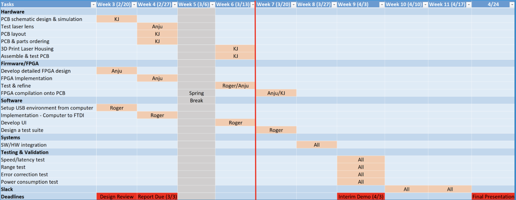
- We shifted Roger to working on the USB interface first and UI later, because the UI can be simple and is not difficult to implement, but USB could prove challenging.
- We added testing lenses and 3d printing a holder to our schedule because it was missing before
- Principles of Engineering, Science, and Mathematics
- High speed digital design
- Optoelectronics
- Photos
- Testing laser diode power and beam width:
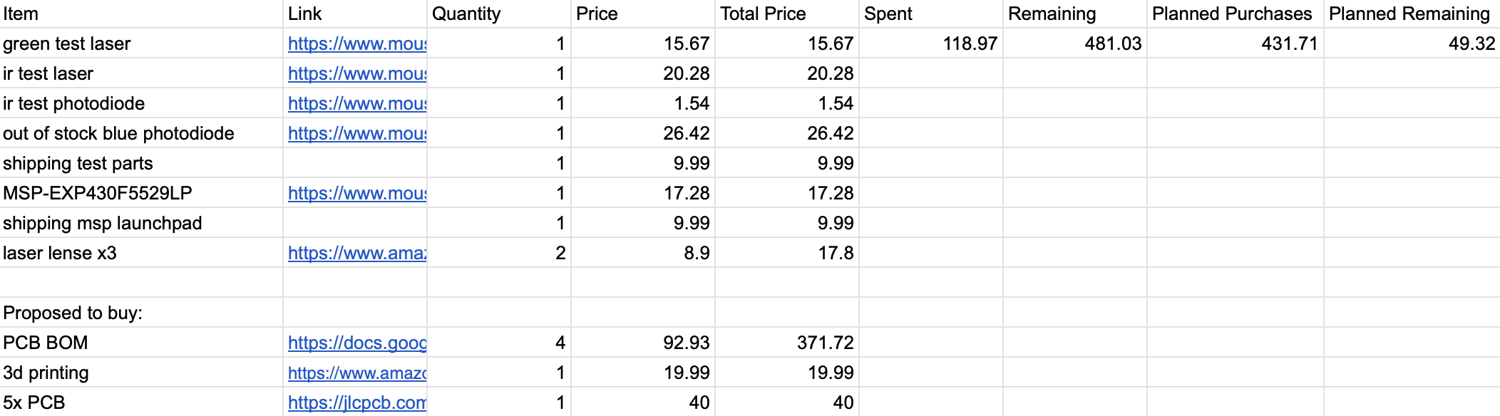
- Budget:
- Testing laser diode power and beam width:
Anju Ito, Roger Lacson, and KJ Newman