- Work this week
- This week I debugged several more issues with our PCB. I continued work on the comparator issue. I tested our two new comparators, but they did not work. In fact, they worked worse. I discovered several things. One is that the comparator overdrive ranges are all specced far better than reality. The other is that this was not the actual issue. The real problem is that our charge pumps create a huge amount of noise. They do not create noise on their outputs. However, the radiated emissions from them induces current in the traces to the photodiodes. Because we measure current on order of magnitude of microamps, this noise is far greater than our signal. To fix this, the charge pumps should be far away from receivers, with long traces carrying the reference voltage over. However, this cannot be fixed without a new board spin. In the end, I fixed this by only using only the green photodiode photodiode, and the charge pump for the IR photodiode plus a voltage divider to get the correct reference voltage. The reason for only using green is explained in the next bullet. Because the photodiode only draws microamps, a voltage divider creates a sufficiently stable voltage. Because the charge pump is far away on the board, it does not radiate emissions into the signal line.
- I discovered that our infrared laser will not work. The laser only creates a 1 mV signal when turned on directly in front of the receiver. I figure that the receiver’s datasheet showing the optical wavelength response is likely inaccurate, since it shows a graph of a full spectrum, and it is unlikely the manufacturer was able to actually measure this, and we are using a laser below the peak wavelength of the photodiode. This is not fixable without redesign or buying a large number more parts to find compatible ones. This, combined with the aforementioned charge pump issue, led me to make the call to remove IR. The green laser functions, and we do not have the budget or time to fix IR, since the components are incompatible.
- I found a solution to our USB power problem. I got usb power/data splitters designed for raspberry pis and modified them for our use. They allow us to combine a 9V3A usb pd supply and a usb 2.0 data wire into a single usb C wire. I made 2 of these boards and verified that both power and data work.
- I spend a lot of time finding correct resistor values to change precise settings and thresholds for both boards. The current state is that both use green lasers set to 5 mW, and both green receivers are set to correct thresholds.
- I 3d printed and tested our lens mounts. They fit and the lenses allow us to focus the lasers. Additionally, since I included the threaded metal piece, the mounts allow us to focus and unfocus the lasers on the fly. This was done by using a belt sander to file them down to be small enough to fit on the board over both lasers and with good focus.
- I ran a quick test with Anju to see if the laser and fpga work together. They do! On the first try, we were able to send data at 6.25 Mbaud using the laser and receiver. This bodes well for us, particularly since this was done with me holding a mirror by hand in front of the laser, making for a bad signal.
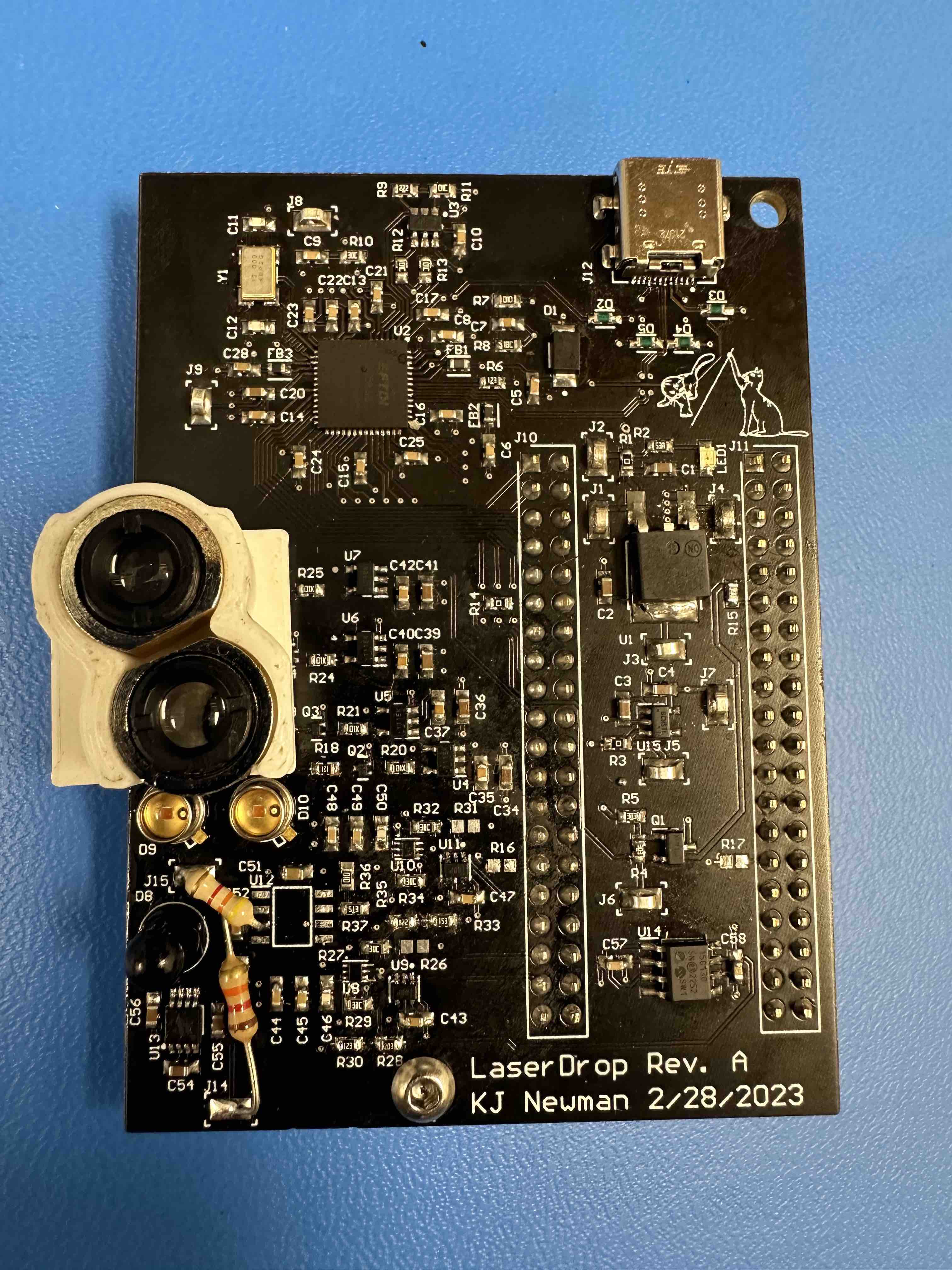
- Image of board now:
- Schedule
- Integration is still behind schedule. Now that hardware seems to be done, this is my number one priority. Since the preliminary test with Anju worked well, and Roger is able to communicate over USB, this seems mostly done. However, we cannot be sure bugs do not remain.
- Deliverables
- Next week, I will finish our second 3d printed housing test. I finished the housing, but I have not assembled and tested it. I also need to use the belt sander to cut the metal pieces down to size.
Anju Ito, Roger Lacson, and KJ Newman