- Risks
- This week we fixed several risks, including low laser power and the FTDI power chip not working. However, we also added several more:
- One is that Macs do not support our usb power plan. We need to find a new power solution. We plan on researching available usb splitters and powered usb hubs that may fit our needs. Worst case, we can either hand splice a wire to separate power and data or we can use a power supply separate from USB. However, we plan on looking into better alternatives than that.
- Another risk is that the comparators do not work. Our original comparators for our receivers do not work as well as the datasheet suggests, and therefore our circuit does not create enough overdrive voltage for them to have digital outputs. To mitigate this, we purchased 2 different new comparator chip models that should perform better. They are the same footprint and will work perfectly if the datasheets are correct. If they both end up not working, we can wire in a breadboard with more analog circuits to fix this. However, that would greatly limit our max communication speed, so we are trying new comparators first.
- Simulation on the FPGA had difficulties running due to subtle syntax differences. The biggest of these were debugged, but the ability to easily verify it might be time-consuming in the future.
- Design Changes
- We will need some new part to fix our usb power delivery issue. This is not yet determined, but will likely be something between our board and the laptop.
- We changed how we will be 3d printing the lens housing. Rather than 3d printing threads or a hole for self tapping, we will cut the metal housing we have down to a small size since it has threads that fit our lens already. Then, we just need to 3d print a circular hole for the housing to sit in, which requires much less precise work.
- We plan on removing the sequence tag ID, once we verify that all of the packets can be performed in-time synchronously. This will be dependent on the speed that the computer can read data off the FTDI, verify the Hamming code, and send data back.
- Updated Schedule
- The actual 3d print and assembly of our lens housing has been pushed to next week due to issues with the board that came up this week.
- Board testing continues to be extended as we encounter unexpected issues with the boards.
- FPGA testing will continue on next week, waiting for software and hardware to work before integration.
- Progress
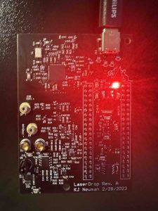
- The board powered over 9V USB PD by configuring the EEPROM connected to the FTDI chip:
- Currently debugging, but a full FSM and datapath for the FPGA was designed and programmed.
- Higher power laser output was produced that can be read better by receivers.
- The board powered over 9V USB PD by configuring the EEPROM connected to the FTDI chip:

Anju Ito, Roger Lacson, and KJ Newman
