- Risks
- The IR receiver on one board appears to be floating. This is not a huge risk because it is likely a poorly soldered part, but there is a risk that there is something big wrong. We will be looking into this next week to determine exactly what is wrong.
- We tried to do a quick test of the receiver, which did not work. This is most likely due to poor setup, but it may require figuring out how the ambient light filtering works, and how best to aim the boards to each other in order to test accurately, which may take some time and work.
- Design Changes
- Our USB connector did not fit properly on our board, so we needed to bend pins and not attach all pins in order to get it connected. This ultimately resulted in some power and ground pins not being connected as planned. This is not expected to cause any issues but does mean that our board supports less current going through the connector now.
- When writing the FPGA program, we’re slightly split on whether to make it so that both lasers must receive at the same time and transmit at the same time. If we do this, it would add integrity because there is a much smaller likelihood that both would turn on accidentally at the same time, and make handling the protocol easier. However, it would also make it so that testing is difficult. Right now, the decision is that it will only handle simultaneous receiving/transmission, and the code will be modified slightly so that testing can be done with just one.
- Updated Schedule
- We did not do any 3d printing this week due to the assembly process taking longer than expected. This will now happen next week.
- The implementation of the FPGA got slightly overlapped with board integration, and some of the code development would be shifted to testing using the actual PCB.
- Progress
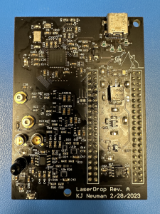
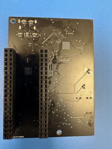
- Boards complete!
- FPGA code written and tested for the laser and receiver module. The FSM that handles the actual protocol behavior is written on the receiver side, but not yet tested.
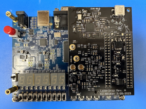
- FPGA and board integrated, and ensured that GPIO pins control the appropriate circuitry.
- Boards complete!

Anju Ito, Roger Lacson, and KJ Newman


