- Work this week
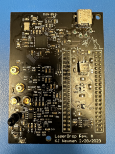
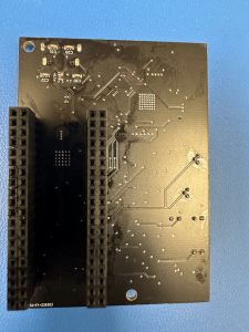
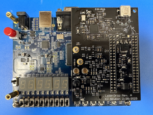
- This week, I assembled two of our PCBs. We did not receive a stencil from JLCPCB, so this took quite a while. The boards assembled as expected with only one exception, the USB connector. The connector requires a board cutout underneath it and the board does not have one, so it took a lot of time to get the connector to fit. Ultimately, I figured out a way to bend the pins and use hot air soldering to get the connector on, but destroyed our 2 other connectors in the process. However, it did work on one board, so we ordered some more connectors to put on the second PCB using the same process. This ultimately will not slow us down much or cost much. The board is shown here:
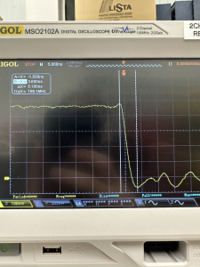
- I also tested the PCBs. The transmission and power circuits work as expected, and the receiver circuits are difficult to test without FPGA software, so I began working with Anju on integrating the FPGA board and the custom board. Transmitting works integrated with the FPGA, and receiving testing is ongoing. All voltages on the board are correct, and laser driving at two different power levels works with sufficient rise and fall time to transmit at our speeds as shown:
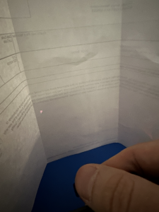
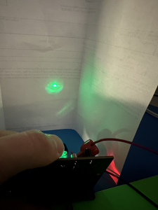
- I verified how the lenses fit over our board and that they properly focus both lasers. I also found that iPhone cameras can indeed see our IR laser, but not very well
- I ordered some additional parts this week. I ordered and received 3d printer filament. I also ordered new usb connectors as we ran out.
- This week, I assembled two of our PCBs. We did not receive a stencil from JLCPCB, so this took quite a while. The boards assembled as expected with only one exception, the USB connector. The connector requires a board cutout underneath it and the board does not have one, so it took a lot of time to get the connector to fit. Ultimately, I figured out a way to bend the pins and use hot air soldering to get the connector on, but destroyed our 2 other connectors in the process. However, it did work on one board, so we ordered some more connectors to put on the second PCB using the same process. This ultimately will not slow us down much or cost much. The board is shown here:
- Schedule
- My work is mostly on schedule. I managed to assemble and test pcbs despite not having the stencil. However, this meant that 3d printing our housing fell behind schedule, and I now plan on doing this next week.
- Deliverables
- For next week, I plan to design our 3d printed housing for the lenses and print it. I also plan on continuing integration of the receiver with Anju and giving a board to Roger for him to integrate USB code and EEPROM settings onto.

Anju Ito, Roger Lacson, and KJ Newman
