What I accomplished :
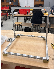
I belted the entire system and remounted the linear ball-bearing mounts. The carriage now travels up and down smoothly across the full stroke. I remounted the LivePin board at the correct spacing from the carriage. I also designed and fabricated the reset mechanism, including two custom acrylic brackets. One set to mount the linear actuators and another to hold the reset plate that clears the pins.
Needs to get done : I need to make sure after programming is done with the 32 servos, to make sure the racks and pinions all interact properly and there are no mechanical faults. Also the final report and video need to be done, along with all servo testing.
This week, we had our demo presentation. We think that our demo went pretty smoothly and the feedback we received was relatively positive. I think we need to work on getting the hardware components finished and printed so that we can connect all the pieces together to get a minimum viable product. Because I had to use the Intel NUC and not the Raspberry Pi that was given, I will need to move all the scripts and the files to the Raspberry Pi and make sure that it can communicate with the STM32 via UART. Crystal and Safiya need to continue working on the firmware and hardware components and finish cutting the dowels and complete the gantry system.
For validation, we need to do more user tests, specifically of the image that is outputted on the pin art board. We will do this by asking a bunch of people if they can see the image that is supposed to be outputted on the board. Additionally, we will do validation for the gantry system and the pin actuator system to ensure that they will push at a certain distance, given an angle. We will ensure that actuators are push pins to the intended heights 95% of the time. We will also make sure that the gantry will move down the belt consistently and with precision and accuracy.
———————————————————————————————–
For Verification of the mechanical subgroup, we will need testing of the gantry, the pin board, and the carriage. For the gantry we will we have the carriage travel up the gantry successfully 5 times, and be reset to its limit switches at the beginning and end. We will also make sure 10 times in a row the carriage travels to the correct row that is authorized by the code.
For the carriage specifically, we will test 3 different combinations of rack and pinion motions. The test will consist of full retraction of all actuators, full extension of all actuators, and actuators at different depths.
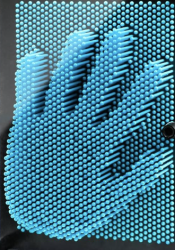
For the pin board, we will test that all pins are stable and able to be controlled by displaying 2-3 images of varying depths and checking through 1/3 of the pins to verify a sample set that the pins are working as they should and are stabilized.
———————————————————————————————–
This week, we partook in demos, which was split up between two main subsections. We had the software component, which showcased the depth camera and the python script that I wrote. We also had the firmware and hardware component, which tested the actuators pushing to max distance. Because our Raspberry Pi did not work before demos, I had to make use of my Intel NUC in order to get our script running and to be able to showcase the work on the software side.
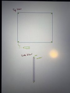
After demos, I was in charge of moving the script to the Raspberry Pi, just so that we won’t have to make use of the Intel NUC in the future. I am also in charge of the UART communication between the RPI and the STM32. Additionally, I am in charge of the reset mechanism, and I drew out plans to get the reset mechanism working. Here is my planned diagram:
As we move towards Thanksgiving break, we are hoping to be able to assemble most of the parts and have a fully working product in the next few weeks.
For the verification system for the software components, we need to make sure that the depth camera is properly calibrated and can display images clearly or at least get enough details to output on a pin board. We will do a bunch of user tests to verify that the image that is outputted is indeed visible. This will be done specifically by asking random people if they can see images are visible, given a diagram of pixels that are shaded in.
I was able to get the LEDs to vary in brightness demonstrating a PWM signal. I am experimenting with different approaches to get 4 servos moving in parallel.
I am behind schedule. I will try to put in more hours to get more progress. Next week I hope to be able to have 4 servos moving in parallel.