Team Status Report 12/6

Unit Testing:

  • Gantry moved up and down 5 times without faults
  • Z-axis limit switch homed the gantry reliably
  • Pin board stability: spot-checked ~1/3 of pins.  All moved freely and stayed seated
  • Reset button triggered linear actuators to retract and clear all pins
  • Quick user test via Google Form
  • Software unit tests: matplotlib visualization
  • Not yet tested: rack-and-pinion row (all-retract, all-extend, mixed depths)

Findings:

User Findings: 

  • Heart: 100% of respondents identified correctly
  • House: 100% of respondents identified correctly
  • Abraham Lincoln:
    – 91% of respondents identified correctly
    – Skull, face, or Abraham Lincoln were considered correct answers
    – 
    Respondents were asked on a scale of 1 to 10 how similar the images on the right were

    • Mean: 6.85
    • Median: 7

Gantry:

Smooth travel on rails, stop within 1 second of limit switch trigger, flips direction on button press.

Team Status Report – 11/22

The most significant risk that could jeopardize the success of the project is when our supplies for the reset mechanism and dowels come in. We are looking into alternatives for the reset mechanism, but the dowels do not have alternatives. No changes were made to the design. I would add pictures but our media quota has been reached.

Team Status Report – 11/15

This week, we had our demo presentation. We think that our demo went pretty smoothly and the feedback we received was relatively positive. I think we need to work on getting the hardware components finished and printed so that we can connect all the pieces together to get a minimum viable product. Because I had to use the Intel NUC and not the Raspberry Pi that was given, I will need to move all the scripts and the files to the Raspberry Pi and make sure that it can communicate with the STM32 via UART. Crystal and Safiya need to continue working on the firmware and hardware components and finish cutting the dowels and complete the gantry system.

For validation, we need to do more user tests, specifically of the image that is outputted on the pin art board. We will do this by asking a bunch of people if they can see the image that is supposed to be outputted on the board. Additionally, we will do validation for the gantry system and the pin actuator system to ensure that they will push at a certain distance, given an angle. We will ensure that actuators are push pins to the intended heights 95% of the time. We will also make sure that the gantry will move down the belt consistently and with precision and accuracy.

———————————————————————————————–
For Verification of the mechanical subgroup, we will need testing of the gantry, the pin board, and the carriage. For the gantry we will we have the carriage travel up the gantry successfully 5 times, and be reset to its limit switches at the beginning and end. We will also make sure 10 times in a row the carriage travels to the correct row that is authorized by the code.

For the carriage specifically, we will test 3 different combinations of rack and pinion motions. The test will consist of full retraction of all actuators, full extension of all actuators, and actuators at different depths.

For the pin board, we will test that all pins are stable and able to be controlled by displaying 2-3 images of varying depths and checking through 1/3 of the pins to verify a sample set that the pins are working as they should and are stabilized.
———————————————————————————————–

Frame Partially Built

Team Status Report – 11/8

This week, we met up multiple times as a team to talk about our progress and work together to get a minimum viable product done for the demo. Safiya worked on 3D printing all our parts and CADing our designs. Additionally, she worked on laser printing our LivePin board. Crystal is working on getting our servos working concurrently. Today we tested how well the servo works on the 3D printed board that Safiya worked on, and it was successful. Tedd finished the software pipeline, but needs to find a better hardware replacement for the Intel Realsense camera and needs a replacement for the Raspberry Pi.

Tomorrow, we will do a full run through of the demo that we are planning on showing. No changes were made to the existing design of the system. Right now, the most significant risks that could hurt this project is if we cannot get communication between the NUC and the STM32. Additionally, if we cannot get a good enough depth camera that could pick up small details, it could really jeopardize our project because our pins won’t be able to output a good enough image.

Here are a few pictures:

Team Status Report – 11/1

Budget is still a big concern for the viability of this project. We currently cannot afford to buy dowels and 32 servo motors, so we are looking for other avenues to get free continuous servo motors. There has been a slight change to the design of the system, specifically the actuator subsystem. Though not specified in any documentation, we originally planned to use 180 servo motors. However, a rotation of 180 degrees is not sufficient enough to actuate the pins. Continuous rotation servos are more expensive, requiring us to spend $50, but I will see if I can hunt for some free ones.

Team Status Report – 10/25

The most significant risk that could jeopardize the success of our project is our project. Some items for the gantry exceeded expect cost of the corresponding items. Due to this concern for budget, the size of the pins might be changing. We are finding alternatives through Ideate, RoboClub, or a more affordable pin solution like straws or chopsticks. Everything for the frame and gantry motion of live pin was ordered and we are waiting on delivery. In terms of the Cad there are some design changes being made to the frame to accommodate for 32×32 frame instead of 32×24. The file for the pin board was made and is ready to laser cut. We found cheapest material at ideate but are waiting to laser cut until we have a finalized pin size based off our budget/supplier.

Team Status Report – 10/18

A – Our product is a low cost alternative to other motorized pin displays. Our low cost and modular approach enables accessibility that can be sourced internationally, allowing replication in museums worldwide. This open and scalable approach encourages cross cultural collaboration in art installations. The ease of use enables users who are not well versed in technology.

B – LivePin is designed with sensitivity to cultural diversity and inclusivity in communication and collaboration. As an interactive system for museums and for children/adults, the device enables users to communicate three-dimensional ideas without reliance on a shared language or cultural context.  This visualization system reduces the potential for misinterpretation of visual or linguistic descriptions and promotes equality regardless of language proficiency. Moreover, by enabling hands-on, physical interaction with digital content, LivePin aligns with cultures that value craftsmanship and learning. The design also respects differing cultural expectations of professional communication by providing a neutral, technology-driven medium for expression and art.

C- Our solution addresses the need for rapid, tangible 3D visualization in classrooms and small exhibits without generating one-off physical waste. Instead of printing and discarding plastic prototypes for every iteration, the system renders forms on a reusable pin board, then resets for the next concept. This directly reduces consumables (no filament, supports, or failed prints) and cuts the time and material tied up in single-use models, while still giving viewers a clear, physical sense of shape and depth.

Environmental considerations are built into the design. The frame uses durable, recyclable aluminum. The guide plates are laser-cut for low scrap, and the pins are wooden dowels that are inexpensive, repairable, and biodegradable. During operation, staged actuation keeps power draw modest relative to continuous additive manufacturing, and the system produces no consumable byproducts once a visualization is complete, the board simply resets. Taken together, the design conserves materials, lowers operational waste, and supports responsible end-of-life handling through reuse and recyclability.

A was written by Crystal. B was written by Tedd J. C was written by Safiya

Team Status Report – 10/4

The most significant risks that could jeopardize the success of the project is the actuator and rack and pinion mechanism not working properly. In order to successfully actuate the pins, we will need this system to work or we will experience speed delays and inaccuracies. Another risk is the depth map not giving us accurate results. This could lead the wrong pins to be actuated even though they are just following the information from the depth map. The first risk is being managed by ensuring that we have proper design requirements so that the hardware does not run into any issues. The second risk is being managed by doing rigorous testing of the depth camera and ensuring that the heightmap from the camera is accurate. Further testing is currently being done to convert the heightmap to a depthmap. We have contingency plans set up to make sure that our product will still be successful. For the gantry system, we can sacrifice speed for more accurate actuation. For the depth camera, we can always find another camera to work with, ensuring that our options are not limited.

There were no changes made to the existing design of the system since the design presentation. We are pretty confident in our design, including the requirements, block diagram, and system specifications. We may run into issues that may require us to pivot from our current design, but so far we are confident in the design.

This is our schedule from the design presentation, and we are still on time with our work with no changes necessary.

A picture of visible progress this week:

Team Status Report 9/27

After further designing our project, we identified several risks. A big concern is actuator reliability. The RC servos may stall, strip gears, or fail to deliver our desired accuracy under load. To mitigate this we will do early bench testing of the servos with the rack and pinion to see if they can deliver the desired results. Another concern is gantry misalignment.
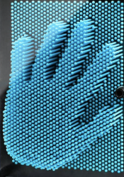
A significant change we made to our design is scaling up our design from 16 x 16 pins to 32 x 32 pins. This change was necessary due to concerns of low resolution. Though you can see Abraham Lincoln with 16 x 16 pins (image below). We originally decide to only have 16 x 16 pins to comfortably afford 16 actuators, but with a more detailed bill of materials we concluded we could afford 32 actuators.


Part A:

The primary purpose of our solution is for entertainment that brings a familiar pin toy concept into a dynamic, automatic form. From a health and well-being standpoint, it offers a playful, low-stress form of interaction. Unlike more physically demanding entertainment technologies, the system is hands-free and does not require repetitive strain, making it safe and comfortable for users of all ages.

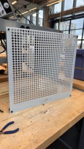
Safety is carefully addressed in both mechanical and electronic design. The pins are covered by an acrylic pane to prevent accidental pinching or injury. Furthermore the reset button acts moves the device into a safe state where pins are reset. Protective housing and controlled motion paths further reduce hazards, ensuring that the entertainment experience remains safe and reliable.

Part B:

Our product solution is designed to foster social connection and shared experiences through entertainment. By transforming the classic pin-art toy into an interactive, automated and affordable display, it creates a platform where groups of people can gather, observe, and engage with the visual output together. This collective interaction encourages conversation, collaboration, and bonding. The system therefore becomes more than just a device. It becomes a medium for social engagement.

Culturally and economically, the product is designed to be versatile and accessible. Its modular, scalable design allows it to be deployed in diverse settings, from well-funded institutions to smaller community organizations, ensuring broader access regardless of resources. By supporting creative expression across different cultural contexts, the system respects and enhances how communities organize around shared interests such as art, technology, or education. In this way, the device not only entertains but also reinforces social ties, offering a playful and inclusive means for people to connect across age groups, cultural backgrounds, and social organizations.

Part C:

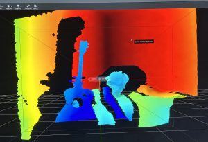
A big focus of our project was creating a 2D to 3D display while being affordable. As any projects that were done before that had actuating pins were extremely expensive and thus making it out of reach for casual applications and environments, such as schools and homes. To accomplish our goal of a live pinScreen, we had to create a mechanism that would push each row of pins, which is mechanically more difficult, but in the long term it is cheaper and more accessible.

Additionally our design controls cost by using a shared actuator head instead of one motor per pin, so resolution scales mostly with low-cost passive parts rather than expensive motors, drivers, and power. Major cost drivers are the frame/linear hardware,  a small set of servos, and the depth-camera/Pi. Operating costs are low , and the architecture lets us scale up affordably by adding pinScreen tiles without redesigning the actuation/control stack.

A was written by Crystal, B was written by Tedd and C was written by Safiya.

Team Status Report 9/20

The most significant risks that could jeopardize the success of the project might be the complexity of the design. Mechanically and Electronically it’s a little complex and out of our comfort zone, the most difficult part that could risk the feasibility is most likely the integration and getting software + firmware + hardware all working cohesively. To manage these risks, we are doing our best to separate each category of the design into different areas of responsibility so that each person will be accountable and an “expert” at their tasks. This will help us when debugging when it comes to the integration stage. Our contingency plan would be scaling down, we are prepared for the firmware and software part to be complicated so we are prepared to drop the “updating” nature of LivePin, and start with pre fed images to replicate on the board, without the human aspect and the “live” feature.

Yes, through concept sketching we found that some sort of clamping mechanism was necessary for the pinboard to stay upright, and we also found the need of limit switches in our design to mitigate the risk of the gantry from damaging itself, and also for the carriage to be able to “home” itself. This change was very necessary, in order for us to have a way to initially find where the carriage is in terms of its cartesian coordinates. This incurs the cost of a couple limit switches which are relatively cheap (less than 15 bucks total).