This week was pretty hectic. Early this week, we had our final presentation, where we presented our final designs and finishing touches on our project. However, we ran into a few issues with some parts, causing us to find alternatives specifically in the firmware. The software components stayed the same and there is still consistency for that portion. However, we have a lot of wires and still need to get servos to get fully working.
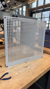
A large part of this week was implementing the reset mechanism. With a transparent plate as our reset plate and with two linear actuators, we were able to fully implement this on our pin board, allowing us to automatically reset the pin board when the image is created.
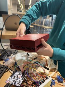
The finishing touches on our product will just be gluing more dowels and wiring the servo motors and finally integrating all the subsystems before the final demos on Monday.
This week, I worked on designing the reset mechanism system and gathering all the moving parts that would feed into the system. In addition to refining this subsystem, I began integrating a Raspberry Pi as the primary controller for communicating with the STM32 via UART. The goal of this setup is to reliably transmit the full 32×32 pin array data, ensuring low-latency, error-tolerant communication between the two devices.
To move toward this, I configured the UART interface on both the Raspberry Pi and STM32 and started developing a structured data-packet format to handle the larger pin-array payloads. Looking ahead, I am planning to build a GUI system on the Raspberry Pi to make the user interface cleaner, more intuitive, and maintainable. This GUI will eventually allow users to interact with the depth camera more intuitively and edit and send the 32×32 pin configurations seamlessly. It would also ideally control the reset mechanism as well.
This Thanksgiving break, I am planning on working on the presentation slides as well.
This week, we had our demo presentation. We think that our demo went pretty smoothly and the feedback we received was relatively positive. I think we need to work on getting the hardware components finished and printed so that we can connect all the pieces together to get a minimum viable product. Because I had to use the Intel NUC and not the Raspberry Pi that was given, I will need to move all the scripts and the files to the Raspberry Pi and make sure that it can communicate with the STM32 via UART. Crystal and Safiya need to continue working on the firmware and hardware components and finish cutting the dowels and complete the gantry system.
For validation, we need to do more user tests, specifically of the image that is outputted on the pin art board. We will do this by asking a bunch of people if they can see the image that is supposed to be outputted on the board. Additionally, we will do validation for the gantry system and the pin actuator system to ensure that they will push at a certain distance, given an angle. We will ensure that actuators are push pins to the intended heights 95% of the time. We will also make sure that the gantry will move down the belt consistently and with precision and accuracy.
———————————————————————————————–
For Verification of the mechanical subgroup, we will need testing of the gantry, the pin board, and the carriage. For the gantry we will we have the carriage travel up the gantry successfully 5 times, and be reset to its limit switches at the beginning and end. We will also make sure 10 times in a row the carriage travels to the correct row that is authorized by the code.
For the carriage specifically, we will test 3 different combinations of rack and pinion motions. The test will consist of full retraction of all actuators, full extension of all actuators, and actuators at different depths.
For the pin board, we will test that all pins are stable and able to be controlled by displaying 2-3 images of varying depths and checking through 1/3 of the pins to verify a sample set that the pins are working as they should and are stabilized.
———————————————————————————————–
This week, we partook in demos, which was split up between two main subsections. We had the software component, which showcased the depth camera and the python script that I wrote. We also had the firmware and hardware component, which tested the actuators pushing to max distance. Because our Raspberry Pi did not work before demos, I had to make use of my Intel NUC in order to get our script running and to be able to showcase the work on the software side.
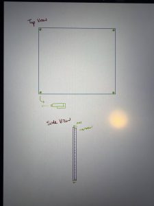
After demos, I was in charge of moving the script to the Raspberry Pi, just so that we won’t have to make use of the Intel NUC in the future. I am also in charge of the UART communication between the RPI and the STM32. Additionally, I am in charge of the reset mechanism, and I drew out plans to get the reset mechanism working. Here is my planned diagram:
As we move towards Thanksgiving break, we are hoping to be able to assemble most of the parts and have a fully working product in the next few weeks.
For the verification system for the software components, we need to make sure that the depth camera is properly calibrated and can display images clearly or at least get enough details to output on a pin board. We will do a bunch of user tests to verify that the image that is outputted is indeed visible. This will be done specifically by asking random people if they can see images are visible, given a diagram of pixels that are shaded in.
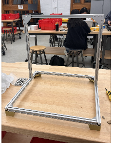
This week, we met up multiple times as a team to talk about our progress and work together to get a minimum viable product done for the demo. Safiya worked on 3D printing all our parts and CADing our designs. Additionally, she worked on laser printing our LivePin board. Crystal is working on getting our servos working concurrently. Today we tested how well the servo works on the 3D printed board that Safiya worked on, and it was successful. Tedd finished the software pipeline, but needs to find a better hardware replacement for the Intel Realsense camera and needs a replacement for the Raspberry Pi.
Tomorrow, we will do a full run through of the demo that we are planning on showing. No changes were made to the existing design of the system. Right now, the most significant risks that could hurt this project is if we cannot get communication between the NUC and the STM32. Additionally, if we cannot get a good enough depth camera that could pick up small details, it could really jeopardize our project because our pins won’t be able to output a good enough image.
This week, I worked on getting the Raspberry Pi script done for the depth camera and the csv output. However, upon setting up the Raspberry Pi, I realized that it is actually faulty. As a result, we will be using my Intel NUC for the time being, just so that we have something to demo on for this week.
The script works well and prompts the depth camera when run, but I suspect that there is an issue with the camera because it is not able to pick up important facial features and details that other cameras should be able to pick up. We suspect that it may be a problem with the Intel Realsense camera and are hoping to find an alternative or purchase another one. It is important for us to be able to have a camera that can pick up small details because our picture will ultimately be downsampled, so if we are already at a disadvantage with our camera quality, we will be at a bigger disadvantage when it comes to our image output on the pin board.
Regardless, I am still able to run the script on the NUC, and it works well. All we need to get done is figure out a way to send the CSV file to the STM32 for further computation and ultimately allow us to push the pins out.
This week, I continued to work on getting the script that I created onto the Raspberry Pi that we acquired for our project. I outlined the steps we need to get this to work. First, I need to install all the required dependencies. Then, I would need to copy the script and data into the Raspberry Pi. Next, I would need to run the Raspberry Pi with a display, and then finally save the CSV so that it could be used for the drivers. This is a very simplified process of what I am currently working on.
The next steps after this to to work with Crystal and Safiya to start getting all the parts working together for our demo. In order to do this, I would need to coordinate with Crystal to make sure all the drivers are working properly, and Safiya to make sure that our design requirements are met and the system is built properly.
This week, I continued developing the depth visualization pipeline using data from the Intel RealSense camera. Building on the preliminary script, I refined the depth-to-plot conversion process to improve the accuracy and consistency of the pin actuation map. I also explored adjustments to the camera’s resolution and filtering parameters, which may lead to noticeably better definition for complex shapes, but it is still a work in progress.
In addition to improving image quality, I began automating parts of the workflow so that depth data can be processed and plotted with minimal manual input. This will streamline testing and make it easier to integrate real-time data processing in future iterations. Overall, the updated system is moving towards a more clearer visual output.
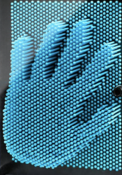
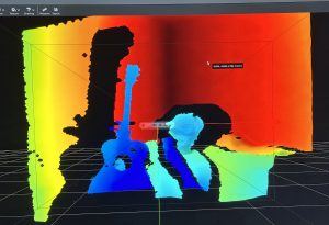
This week I worked on getting a visible plot from depth coordinates provided by the Intel Realsense. With my preliminary python script, I was able to run OpenCV and matplotlib to get a pretty good output of which pins should be actuated and the distances that each pin should be actuated. Here are a few examples below:
As you can see, the depth camera was pretty accurate and is able to capture simple objects and display them pixelated on a plot. However, I realized that more complex objects like faces are not well translated onto the plot. I might have to fix up the resolution of the depth camera and see if that could help us get better results. For now, this is a preliminary script and it seems to be working well. I will automate this process in the future as well.
The most significant risks that could jeopardize the success of the project is the actuator and rack and pinion mechanism not working properly. In order to successfully actuate the pins, we will need this system to work or we will experience speed delays and inaccuracies. Another risk is the depth map not giving us accurate results. This could lead the wrong pins to be actuated even though they are just following the information from the depth map. The first risk is being managed by ensuring that we have proper design requirements so that the hardware does not run into any issues. The second risk is being managed by doing rigorous testing of the depth camera and ensuring that the heightmap from the camera is accurate. Further testing is currently being done to convert the heightmap to a depthmap. We have contingency plans set up to make sure that our product will still be successful. For the gantry system, we can sacrifice speed for more accurate actuation. For the depth camera, we can always find another camera to work with, ensuring that our options are not limited.
There were no changes made to the existing design of the system since the design presentation. We are pretty confident in our design, including the requirements, block diagram, and system specifications. We may run into issues that may require us to pivot from our current design, but so far we are confident in the design.
This is our schedule from the design presentation, and we are still on time with our work with no changes necessary.