What I accomplished :
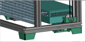
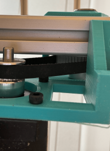
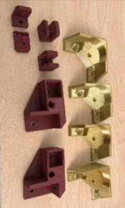
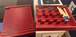
I belted the entire system and remounted the linear ball-bearing mounts. The carriage now travels up and down smoothly across the full stroke. I remounted the LivePin board at the correct spacing from the carriage. I also designed and fabricated the reset mechanism, including two custom acrylic brackets. One set to mount the linear actuators and another to hold the reset plate that clears the pins.
Needs to get done : I need to make sure after programming is done with the 32 servos, to make sure the racks and pinions all interact properly and there are no mechanical faults. Also the final report and video need to be done, along with all servo testing.
Pin board stability: spot-checked ~1/3 of pins. All moved freely and stayed seated
Reset button triggered linear actuators to retract and clear all pins
Quick user test via Google Form
Software unit tests: matplotlib visualization
Not yet tested: rack-and-pinion row (all-retract, all-extend, mixed depths)
Findings:
User Findings:
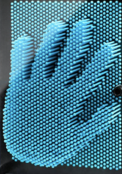
Heart: 100% of respondents identified correctly
House: 100% of respondents identified correctly
Abraham Lincoln: – 91% of respondents identified correctly – Skull, face, or Abraham Lincoln were considered correct answers
– Respondents were asked on a scale of 1 to 10 how similar the images on the right were
Mean: 6.85
Median: 7
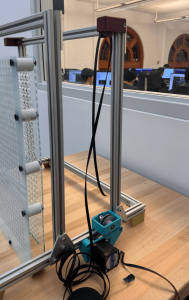
Gantry:
Smooth travel on rails, stop within 1 second of limit switch trigger, flips direction on button press.
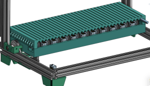
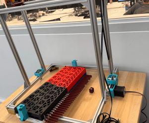
This week was a grind to finish really all the mechanical components of LivePin. I believe it is 2/3 of the way there. There were a few bumps in the design that caused me to take some more time drilling a couple holes to make the gearboxes fit, but so far I have all the 3D Printed parts other than the pinions and reprints of the feet. I was able to assemble the full frame and carriage (without servos), and am now working on the gantry, I assembled 1 out of 2 of the gearboxes and started belting it today. I superglued the bearing plates to the carriage, and am letting it set till tomorrow. I also made edits to the pin board by putting on 10 spacers.
Assembled Carriage with bearing mountsBelt and gearbox on frame, plus spacers on PinBoard
Goals for Next Week: Handoff LivePin to programming on Tuesday at the latest. Finish testing by Sunday. This also includes smaller goals like printing all pinions by Tuesday, finish assembly of gearboxes and belts, as well as assembling the pin board.
On Schedule: Yes but rushing
Question of the Week: Knowledge I found necessary to learn was research, design, and execution. Although tedious and at times hopeless feeling, research and designing in CAD were so crucial once I reached assembly. The time I put into a thoughtful design is now paying off as the construction comes to life and the moving parts start to fit together. Another strategy is research, I had no idea how to make a “LivePin” or a tool that goes up and down and pushes pins, so I looked for parallels and studied those. I could not find any LivePin type devices, so I looked at how 3D printers are built. That research was the basis of the design and made things work. I also learned to prioritize purchasing even when the design was not as far along as I wanted. Knowing to reprioritize was crucial.
The biggest new skill was talking to people who could help. I introduced myself to laser cutter monitors, Robo Club managers, and the machine shop manager, and they helped with both fabrication and sourcing (bolts and acrylic). Those connections were actually fun and very useful for reality checks. For example, I was ready to 3D print 1,024 pins until a TechSpark woodworker suggested using dowels instead, which saved time and money. These are the strategies I am keeping: Research and design (thoroughly), use your available resources, and learn to reprioritize when necessary.
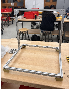
This week my priority was Frame/Gantry Assembly and 3D printing. I made significant progress and am proud to see the design from CAD coming to life.
I printed the feet of the frame and partially assembled the frame of LivePin. I also finished the hopefully final design of the carriage, where I added lightning holes, made the mounting holes. for the servos bigger, and increased the size of the rack slides to allow for easier sliding this time around. I finished printing it! And now need to assemble it on Sunday and design the mount for it onto the frame.
I also printed 16/32 racks, no pinions yet, and printed most of the components. I aim to finish 3D printing by this Wednesday. I also aim to have the frame completed by Sunday, and mount the carriage and belt by Friday.
I am a little rushed for time, but I am ahead of the schedule on the update Gant Chart.
Frame Partially Built3D printed Feet, and belt printsCarriage Fully Printed
I will be breaking up the accomplishments and goals into three categories, carriage, frame/gantry, and pin board. As all three had progress in either CAD/Design, Fabrication, or Assembly.
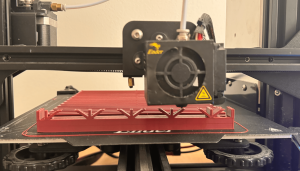
Carriage: I completed a “working” version of the carriage CAD, and began printing it. I split it into two for printing purposes as it was too big for my ender 3. The bottom print of the carriage took 17 hours, and the top took the same. It was crucial to have these done before last Friday as we prepped for demo. I updated the design of the racks to make them longer and the pinions to make them work with the 180 degrees servos instead of continuous ones. I printed 6/32 of the pinions and 4/32 racks.
Once everything was printed, then began the testing. I had to file the carriage down to make the racks slide smoothly, but once finished the racks moved really nicely. The pinions had problems mounting to the servos, so those had to be redesigned once more, and are currently printing.
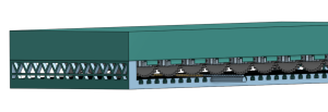
3D Printing bottom half of carriageCarriage with rack pushing pin on pin boardCarriage Assembly with pins and servo
The carriage works enough for demo, but needs some design changes and to be reprinted. I will be adding lightning holes for both weight, and room for the wires to pop out. I will also be increasing the size of the mounting holes. This redesign will take some time, and so I will allocate a good chunk of next week to it, in order to get it printed on time. I plan to get the design done this coming week and start printing again on Saturday. I also plan to print a majority of the rack and pinions throughout this week .
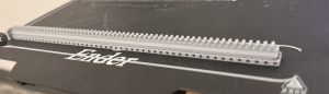
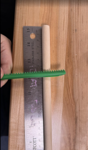
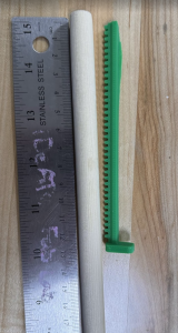
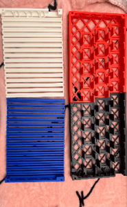
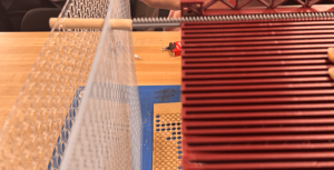
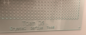
Pin Board: The Pin Board got two iterations this week. I finished the cad of the pin board on Sunday and laser cut it. The outer frame of the board wasn’t large enough to fit on the frame, and needed adjustment, another slight detail was the spacing on the holes, I ended up moving them closer together and fixing some geometry to make the carriage be able to reach all rows of the pin board. It now looks like this, with both boards assembled and spacers in between.
The dowels were calculated to need 5cm of offset, 1/8″*2 for the thickness of the pin board, 1″ for spacing in between boards, and 2 mm of clearance. A few were cut, and put on the board. Next week I hope to order all the dowels we need, and have them ready to cut for the week after.
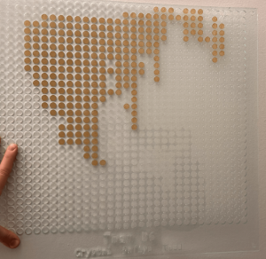
Newest Pin Board Print, with engravingLeftover stickers display how an image can look on the pin board
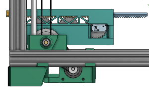
Frame/Gantry: We made some progress in getting pieces for the frame and gantry repurchased, and I believe we have everything except the heat inserts. I made some progress on the full assembly cad, but need to design the gearbox mounts, and the connections between the carriage and the frame. There is also a lot of assembly work to get done, I will hopefully assemble the frame next week and design the gearbox plate and the piece that connects the carriage with the frame.
CAD for Gearbox mount, not fully complete
Progress: On schedule, but a little tight on time for 3D printing and design.
Redesigned pinions to work for 180 degree servos, thus causing a redesing in the carriage. It got larger and all spaceing between servos were adjusted. I finished the CAD of the carriage.
I got my 3D printer working, made adjustments to the rack design, and got the first nice print of a rack. I am now starting to print the pinions, and then hopefully Sunday, the carriage.
I redid purchasing, as some of our Amazon purchases got lost due to the AWS crash event.
I am now designing the Z axis gantry system and gearbox, hopefully full CAD done by Monday.
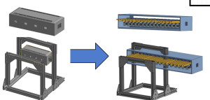
Here is the progress so far on the full assembly CAD, I included a before, so the progress can be shown, the first design (which is actually a second design) is all over the place and unfinished, more of a proof of concept, and the finalized design is the one that is more clean, with belt and stuff to proportion. It still has a couple more tweaks but will hopefully be done this Monday (11/3).
Pin Board is also a work in progress, especially designing its mounting system
A few design questions moving forward:
– Is one set of bars enough to support the carriage ?
– Is one pin board enough to support the pins?
– Where can reset mechanism go? (after, V3)(before, V2)
This week I pushed purchasing and fabrication forward. I submitted all purchase requests for the frame and motion system, revised the cart to swap in cheaper equivalents, and removed a few non-essential frame parts to stay in budget. I also brought my 3D printer back online and printed a first rack-and-pinion set, the print has defects, so I started tuning the printer. On the pin board, I went to TechSpark planning to laser cut but they didn’t have the right sheet size. I checked Ideate and confirmed they have acrylic that fits. Back on CAD, I re-checked cost and realized 1,024 dowels would strain the budget, so I explored alternatives: bulk chopsticks were cheap but too small in diameter, at Robo Club I found PVC stock that could work. I contacted the shop manager to request material.
I’m generally on schedule for frame and motion procurement, but the pin board is waiting on final material choice. To stay on track, I will finalize the pin diameter and hole pattern as soon as I hear back on the PVC, size the laser files accordingly, and cut at Ideate. In parallel I’ll finish the printer tuning and re-print the rack and pinion so mechanical tests are not blocked.
My Goals:
Finalize pin-board design with confirmed pin material and diameter, plus laser ready DXF.
Pin board laser-cut at Ideate and a small assembled section for testing.
Reprint, clean rack-and-pinion set and a short note on print settings and tolerances.
Updated BOM with actual unit prices from the approved frame/motion orders and removal of the unused components.
I finished the CAD for the carriage subsystem. I started fixing my 3D printer to get ready to print rack and pinions. I also put in purchase requests for all items so far to assemble LivePin. I had to also redo the CAD for the frame because we went from 32×24 in the CAD to 32×32 pin board.
Behind. Purchasing might take a bit. To get ahead I will ensure all items are ordered that we need for a working demo, and get the CAD to a point where all pieces are accounted for.
Fully Finished CAD, 3D printed rack and pinions, and finished purchasing.
This week I focused on our design presentation and hardware planning. I practiced the presentation several times, and moved the bill of materials forward by organizing parts by subsystem, choosing likely vendors, and building rough cost totals. I also updated CAD for the larger pin screen and produced visuals for the presentation.
I am a little behind on final pricing and carriage design. To catch up I will lock vendor choices, complete the latest bill of materials with totals and start the first round of orders so the build stays on track.
Next week I plan to finalize the bill of materials, finish the carriage design and begin 3D printing the rack and pinions.
This week I spent a lot of time on Onshape CADing and redesigning. The original CAD that I started earlier in the week derailed a bit, as we got to discussing some design changes, specifically centered around increasing the resolution of the PinScreen. As it scaled up, the frame and gantry and carriage all had to scale up as well. We then decided on Monday to make a custom PinScreen instead of buying a COT one, and thus that led to needing to design and CAD the PinScreen. I am not totally done with a lot of the details (haven’t started the reset mechanism). But this is the progress so far on the cad :
Deliverables for next week would be a complete Bill of Materials, Purchasing done, and a more fleshed out CAD that is ready(ish) for assembly. This includes the design and CAD of the carriage 3D print, which is the most complicated, the motors and belts on the frame, and the pinScreen reset mechanism.

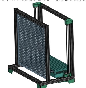 (after, V3)
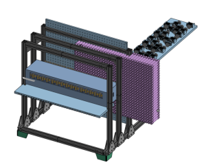 (before, V2)