This week, we met up multiple times as a team to talk about our progress and work together to get a minimum viable product done for the demo. Safiya worked on 3D printing all our parts and CADing our designs. Additionally, she worked on laser printing our LivePin board. Crystal is working on getting our servos working concurrently. Today we tested how well the servo works on the 3D printed board that Safiya worked on, and it was successful. Tedd finished the software pipeline, but needs to find a better hardware replacement for the Intel Realsense camera and needs a replacement for the Raspberry Pi.
Tomorrow, we will do a full run through of the demo that we are planning on showing. No changes were made to the existing design of the system. Right now, the most significant risks that could hurt this project is if we cannot get communication between the NUC and the STM32. Additionally, if we cannot get a good enough depth camera that could pick up small details, it could really jeopardize our project because our pins won’t be able to output a good enough image.
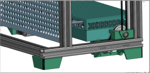
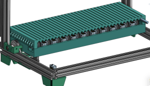
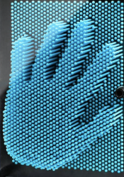
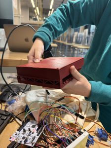
Here are a few pictures:
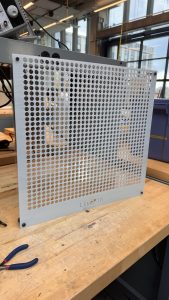
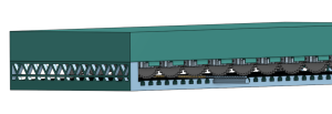
 (after, V3)
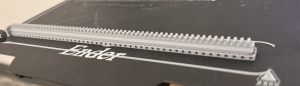
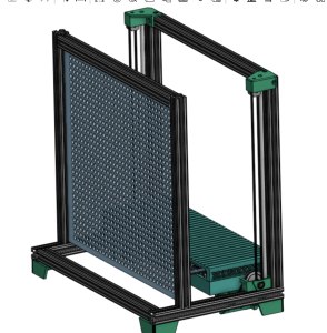
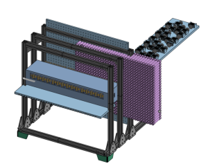 (before, V2)